Pair of saw blades

a saw blade and blade body technology, applied in the field of blade body pairs, can solve the problems of affecting the operation, affecting the quality of saw blades, and prone to falling off or quickly being worn down, and achieve the effect of reducing the friction of the blade body and facilitating the milling of the cutting elements

Inactive Publication Date: 2010-03-11
TWINBLADE TECH HLDG SWEDEN
View PDF25 Cites 4 Cited by
  • Summary
  • Abstract
  • Description
  • Claims
  • Application Information

AI Technical Summary

Benefits of technology

[0005]Against this background, the object of the present invention is to obviate the disadvantages of the known solution and to provide a pair of saw blades that works rather quiet and operates more safely and in addition is easier to produce.SUMMARY OF THE INVENTION
[0007]According to the invention by providing the cutting elements with a first and a second overhang, grinding of the cutting elements is made a lot easier and thus producing too, because all contact between the sheet material of a blade body and a grinding disc used for grinding is easy to avoid. In addition, the overhangs contribute to breaking of chips, that penetrate between two cutting elements meeting each other, in a free space, which is formed by the overhang in question immediately behind the cutting element as to the sense of rotation, thus preventing the formation of long chips, which tend to get stuck between the saw blades. The ridge / ridges, which is / are easily made by turning or milling of the blade body / bodies before the cutting the cutting elements are attached, have no interruptions, which reduces operational noise and prevents operating interruptions because of chips that during operation enter into the space between the blades. Further, such a ridge / ridges is / are very durable and can withstand high working temperatures that occur during sawing.
[0009]According to a preferred embodiment, the cutting elements besides said first and second overhang on the sides facing each other have overhangs on their opposite sides too. Of course the latter overhangs also facilitate the milling of the cutting elements and further they contribute to a reduction of the friction of the blade bodies against the cut material.

Problems solved by technology

A disadvantage with the extended cutting elements according to the international patent application is that there are small intervals between the individual cutting elements, which during operation entails both noise and a risk of saw dust and the like entering in between the saw blades, thus jeopardizing operation.
A disadvantage with the other spacer means is above all a tendency to fall off or to quickly be worn down during operation, a tendency further promoted by high temperatures occurring during sawing.
In addition, in the known solution with the extended cutting elements grinding of the cutting elements causes problems.
This is due to the fact that the opposing blade in such a solution is forced to have cutting elements that do not protrude from the blade body in question, and for that reason during grinding these of these cutting elements one has to count on problems with grinding wheels being clogged by the sheet metal of the blade body, said sheet metal being inevitably affected by the grinding.

Method used


Image

  • Pair of saw blades
  • Pair of saw blades
  • Pair of saw blades

Examples


Embodiment Construction

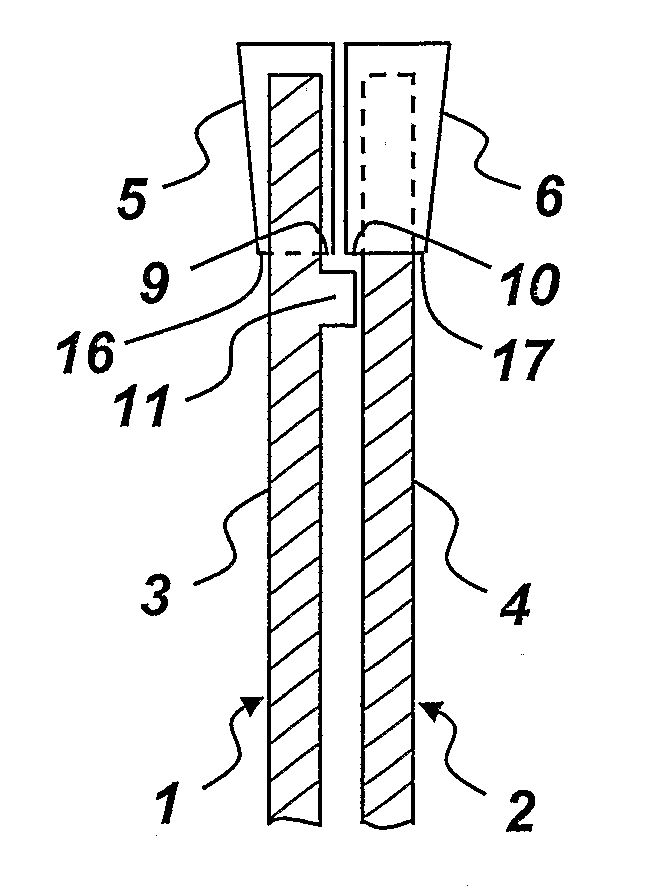
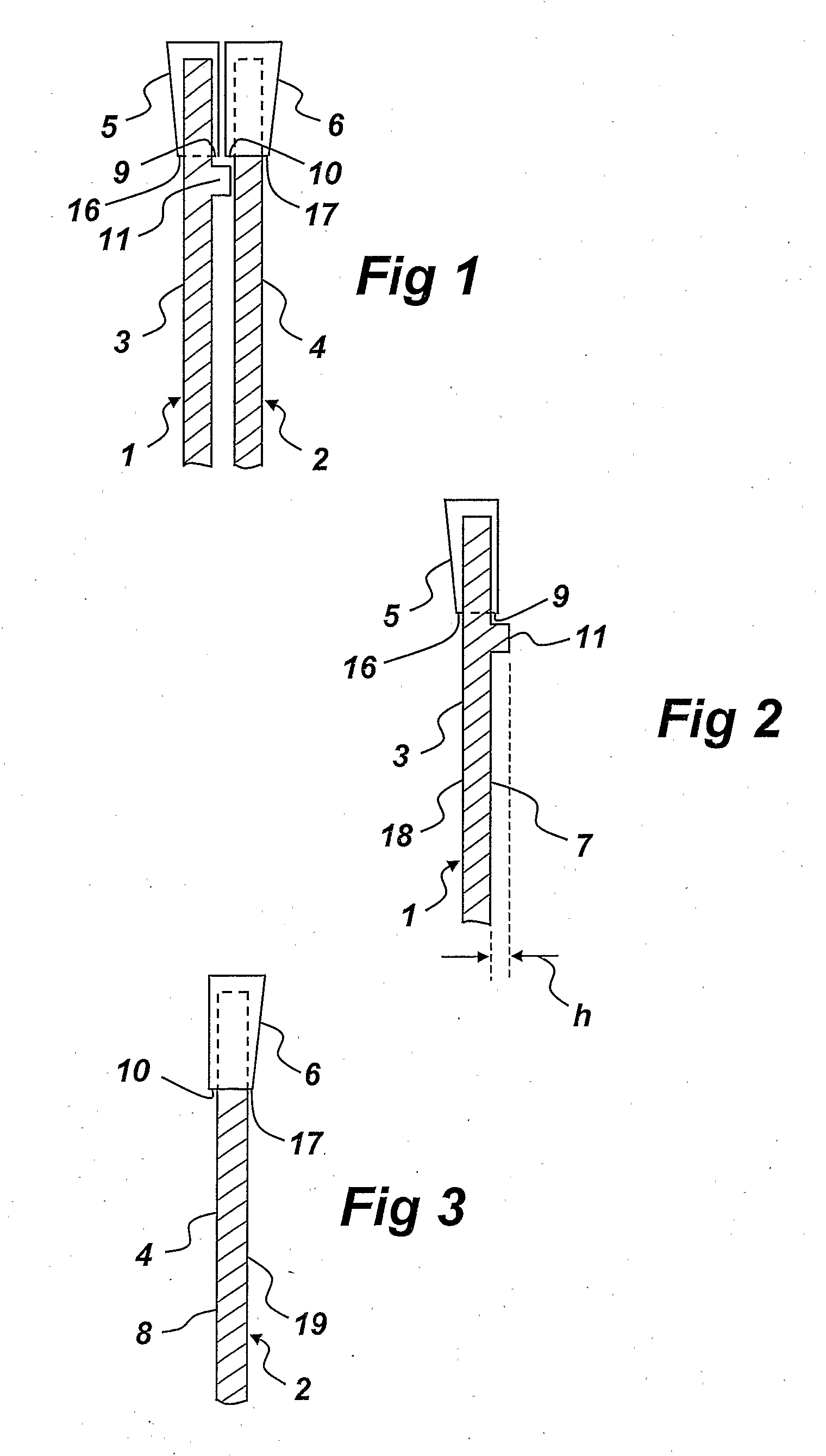
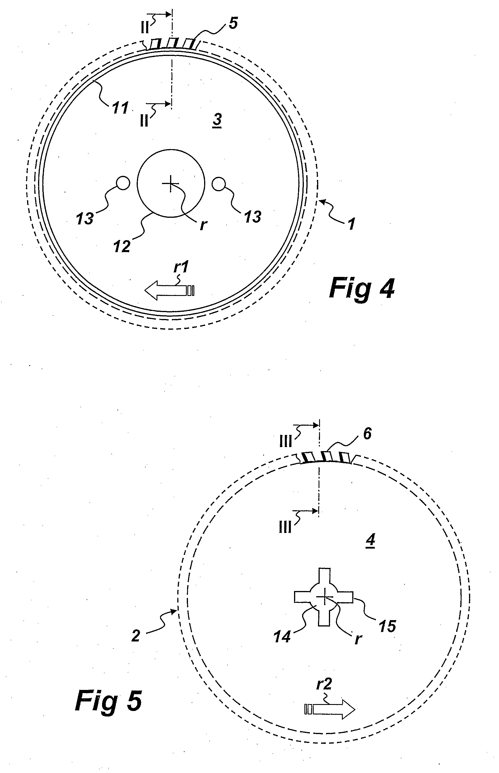
[0016]In FIG. 1 a pair of saw blades is shown, that consists of a first blade 1, which is arranged to rotate around a rotational axis r according to FIG. 4 in a first direction r1, and a second blade 2, which according to FIG. 5 rotates in a second direction r2, opposite to said first direction r1. Such an opposite rotation of the blades 1, 2 does effectively counteract all tendencies of throw and in addition it enables very high work rates.

[0017]Each blade 1, 2 has its own blade body 3, 4, which appropriately is made of sheet steel. Each blade body 3,4 has cutting elements along the periphery thereof, which in the embodiment shown are saw teeth 5, 6 with cutting edges of hard metal brazed thereon.

[0018]The saw teeth 5, 6 have, which is best shown in FIGS. 2 and 3, a slightly larger width than the associated blade body 3, 4. This means that the saw teeth 5 of the first blade 1 protrudes with a certain overhang 9 from the front side 7 of the blade 1, that is the side that is intended...


PUM

PropertyMeasurementUnit
angleaaaaaaaaaa
heightaaaaaaaaaa
temperaturesaaaaaaaaaa

Abstract

The invention concerns a pair of saw blades, including a first blade (1) and a second blade (2), which are arranged to rotate around the same rotational axis in opposite directions. Each of the blades (1, 2) has its own blade body (3, 4) and peripheral cutting elements (5, 6), wherein the blade body (3) of the first blade (1) has a front side, which is turned towards a back side of the blade body (4) of the second saw blade (2), and wherein the cutting elements (5, 6) form overhangs (9, 10) protruding from said front or back side. Said front and / or back side have / has a circumferential ridge (11), which is arranged peripherally inside of the cutting elements (5, 6) and to slide over a corresponding part or a corresponding ridge (11) on the opposite back side and / or front side, wherein the ridge / ridges (11) is / are made in one piece with the blade body (3, 4) in question and serves / serve as a spacer means to prevent the cutting elements (5, 6) with their overhangs (9, 10) to hit each other during rotation of the blades (1, 2).

Description

TECHNICAL FIELD[0001]The present invention concerns a pair of saw blades, including a first blade, which is arranged to rotate in a first direction around a rotational axis, and a second blade, which is arranged to rotate around the same rotational axis in a second direction opposite to the first direction, wherein each of the blades has its own blade body and cutting elements along the periphery of each blade body, the cutting elements being arranged to run close to and in parallel with each other during rotation, and wherein the blade body of the first saw blade has a front side, which is intended to be turned towards a back side of the blade body of the second saw blade.STATE OF THE ART[0002]From the international patent application WO02 / 092298 it is known to arrange a spacer means between two cooperating saw blades in order to prevent the cutting elements from hitting each other. In this known solution, the spacer means consists of either radially extended cutting elements on on...

Claims


Application Information

Patent Timeline
Patent Type & Authority Applications(United States)
IPC IPC(8): B27B33/08B23D61/02
CPCB23D45/10B23D61/02B23D61/026Y10T83/9319Y10T83/9374
Inventor ERICSSON, HANS
Owner TWINBLADE TECH HLDG SWEDEN
Why Eureka
Try Eureka