
Straight-line piston fluid engine with wobble drive valve actuation

a technology of wobble drive valve and straight-line piston, which is applied in the direction of positive displacement liquid engines, oblique crank gearings, gearings, etc., can solve the problems of reducing the power of the engine, reducing the efficiency of the engine, and requiring frequent lubrication of the piston, so as to reduce friction and eliminate side forces of the piston. , the effect of easy scaling

Active Publication Date: 2010-03-11
GREEN ROBERT R
View PDF4 Cites 5 Cited by
  • Summary
  • Abstract
  • Description
  • Claims
  • Application Information

AI Technical Summary

Benefits of technology

[0005]The object of the present invention is to provide improvements to axial piston engines by providing a modular engine with variable number of cylinders that is easily scalable for large and small applications. It is further object to reduce friction by eliminating side forces to the piston. This is accomplished by providing straight-line movement with fewer parts. Reduced weight of reciprocating mass and minimal lubrication requirements are the results of this new arrangement. The valve arrangement allows room for large port sizes for the free flow of fluids. The economy of structure facilitates uncomplicated and economical manufacturing.
[0007]The axial reciprocating movements of the piston disks are converted into uniform rotation of the crankshaft with greater economy of parts and less reciprocated mass. By means of the forgoing arrangement, the piston drive point displacement along the arcuate path of the wobble drive member is transformed into a straight-line movement of the piston disks within the cylinders. A single “O” ring seal can thus be employed to seal the piston disk within the cylinder wall. Reduced contact between the piston disks and the cylinder walls result in less friction and minimal lubrication requirements. Advantageously, saturated steam can provide adequate lubrication under normal operation.

Problems solved by technology

The engines are relatively heavy for the power they can produce.
The pressure on the pistons, joints and seals require frequent lubrication in places that are not easily accessible.
Worn seals and joints are not easily replaced.
No such engine has been adopted for use on a wide scale.
The lack of commercial exploitation of this type of engine is probably due to the relative high cost of manufacture as well as maintenance and lubrication issues.
Scaling for large and small engines may also be problematic due to the confined space for valve plumbing and actuation.

Method used


Image

  • Straight-line piston fluid engine with wobble drive valve actuation
  • Straight-line piston fluid engine with wobble drive valve actuation
  • Straight-line piston fluid engine with wobble drive valve actuation

Examples


Embodiment Construction

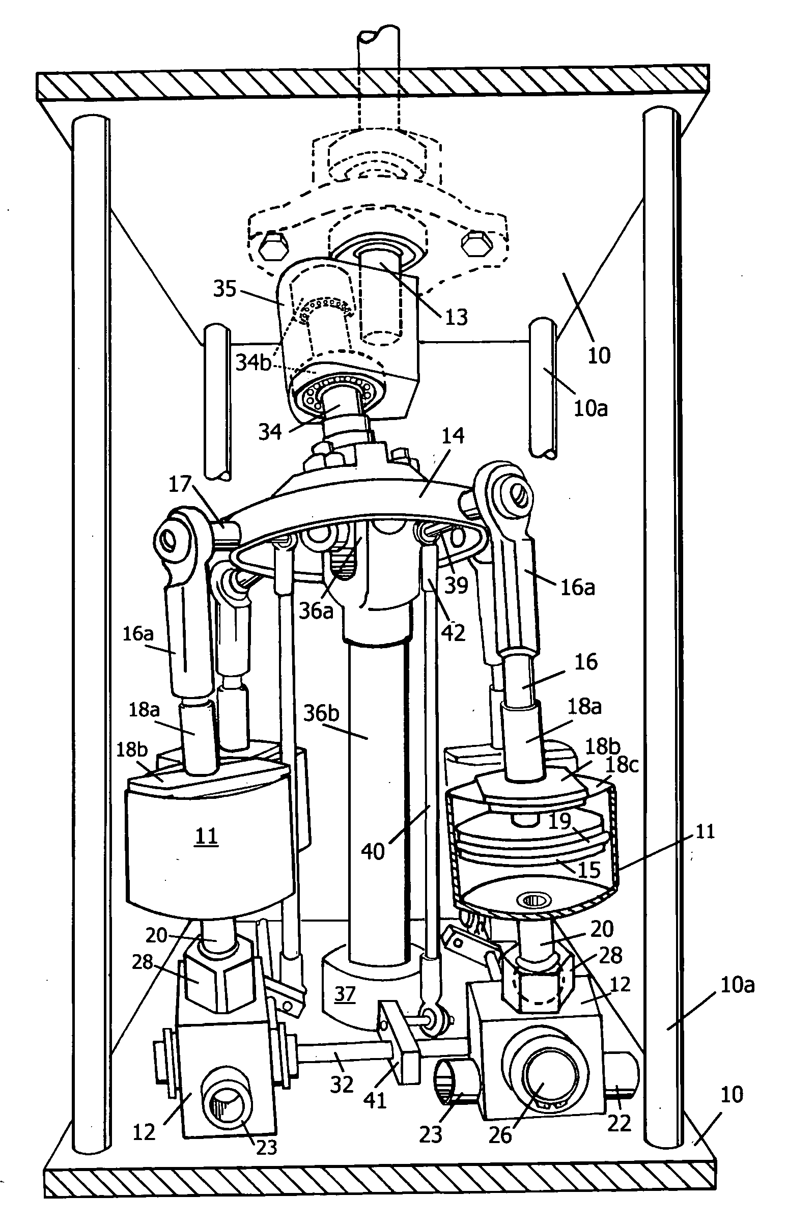
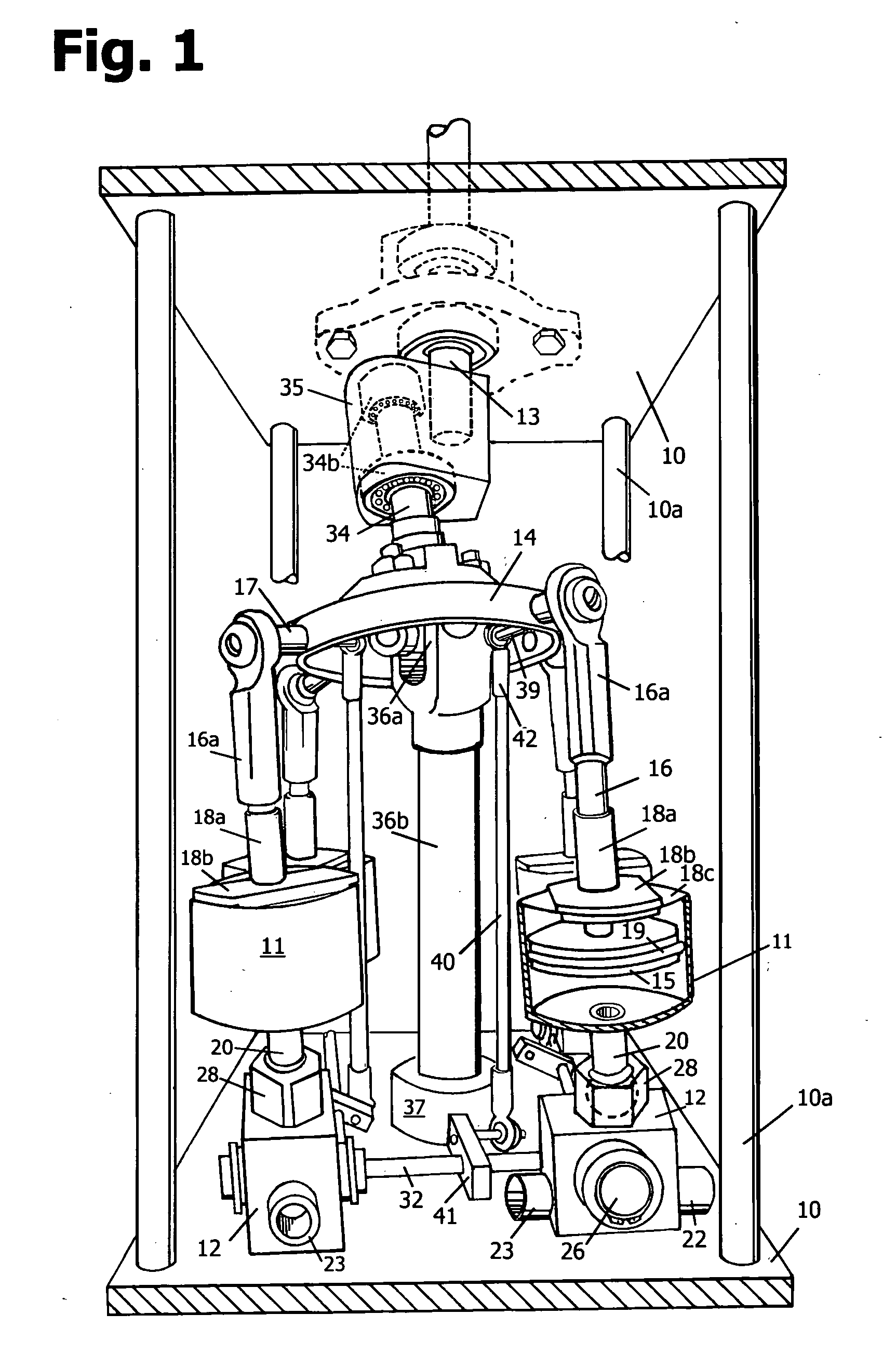
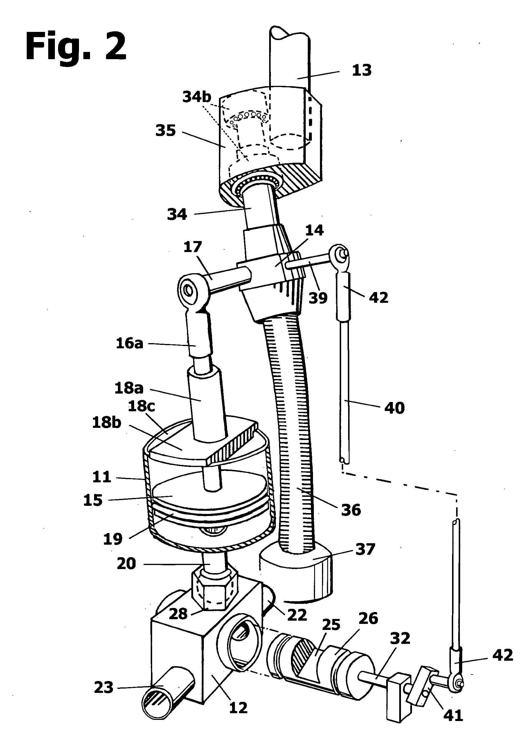
[0015]Referring to the drawings in detail, FIG. 1 illustrated as the preferred embodiment an axial-piston engine having a frame assembly with four legs 10a connecting two end walls generally referred to by numeral 10 supporting in proper operational relationship four basic components consisting of four identical, articulating cylinder assemblies 11, pivotally attached to fixed steam induction valve assemblies 12, an output crankshaft 13, a wobble drive member 14 operatively interconnecting the cylinder assemblies with the crankshaft.

[0016]Cylinder assemblies 11 as shown in FIG. 1 and FIG. 2 consisting of a cylinder pivotally connected to valve assembly 12 by a ball swivel-socket joint 20. Tube 20 is fastened to the bottom of the cylinder and contains a hollow ball made of a durable metal or ceramic material and fits pivotally into an equally durable swivel-socket joint 28 that is replaceably joined to valve 12. A piston-disk 15 within the cylinder is displaceably connected by a conn...


PUM


Abstract

An axial piston fluid engine having single-acting cylinders incorporating swivel-joint attachment of the cylinders to rotary control valves wherein straight-line piston movement is established for the elimination of side forces on the pistons. The pistons and the control valves are operatively connected to a common wobble drive member and arranged in geometry of lever positions to coactively time the drive fluid into and out of the cylinders intermittently.

Description

BACKGROUND OF THE INVENTION[0001]This invention relates to an axial piston fluid engine with single-acting cylinders pivotally attached to rotary valves that are actuated by a wobble drive member.[0002]Axial piston steam engines of the type having a plurality of pistons along parallel axes pivotally operated by a wobble plate mechanism are known in the art. An example may be seen in U.S. Pat. No. 4,491,057 (Ziegler, 1985). As in other examples such as U.S. Pat. No. 4,106,354 (Girodin, 1978), the engines are encased in a rigid block and have fixed, stationary cylinders. The pistons have ball-jointed piston rods that push and pull a wobble plate mechanism to convert the piston motion into rotary movement.[0003]The engines in these examples have many precisely machined parts and castings as well as an engine block for encasement. The engines are relatively heavy for the power they can produce. The pistons are subject to side pressures from the angular piston rod alignment. Additional p...

Claims


Application Information

Patent Timeline
IPC IPC(8): F01B3/10F01B3/02F16H23/08
CPCF01B3/0002Y10T74/18336F01B3/0094
Inventor GREEN, ROBERT R.
Owner GREEN ROBERT R
Learn More