
Internal Gas Pressure Resistant Metal Pop-Top Cover and Method of Making

a metal pop-top cover and gas pressure resistant technology, applied in the field of pop-top covers, can solve the problems of unstable lids and slippage, and achieve the effects of reducing the diameter of the material notch, saving lid materials, and economizing on materials

Active Publication Date: 2010-03-11
SUZHOU SLAC PRECISION EQUIP CO LTD
View PDF19 Cites 12 Cited by
  • Summary
  • Abstract
  • Description
  • Claims
  • Application Information

AI Technical Summary

Benefits of technology

[0004]The present invention provides an atmospheric pressure-resistant metal pop-top cover that is designed to resolve the conflict between material savings and the maintenance of pressure resistance in a pop-top cover so that the pop-top cover still provides relatively high atmospheric pressure resistance while the material's notch diameter and thickness are decreased.
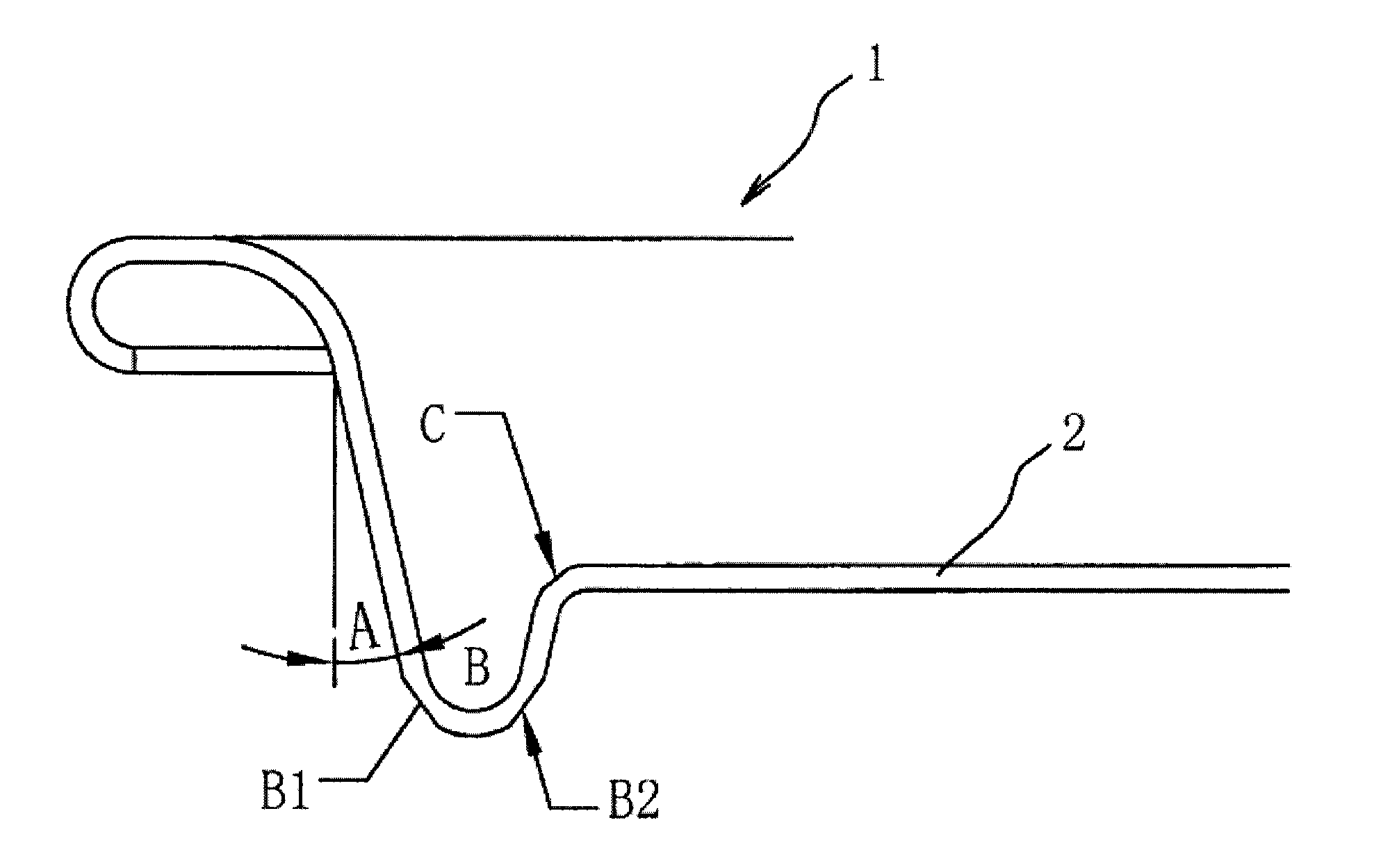
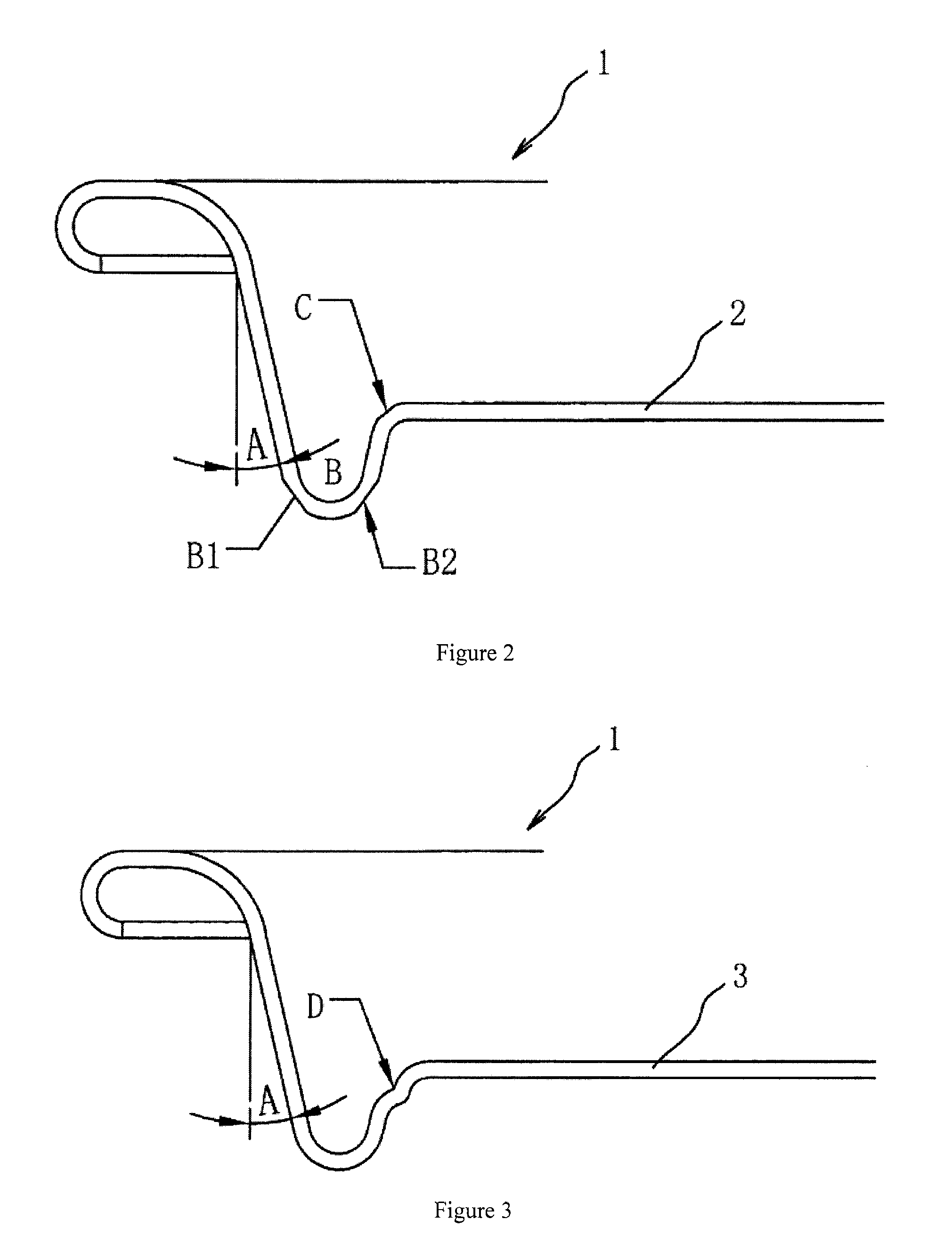
[0009]3. The principle of this invention is: Increasing the angle A in a cover of the same type in a range of 15-60 degrees enables the material notch diameter of the pop-top cover to be increased, the utilization ratio of the pop-top cover to be increased, and a savings to be realized in the production cost of the pop-top cover. However, this may decrease pressure-resistance strength. In order further to maintain pressure resistance after increasing angle A, in the present plan, local cooling and hardening treatment of the bottom segment B of the lid and segment C of the intermediate rise is performed at the same time through forging and pressing; that is, the arc-shaped segments B1 and B2 and the rise segment C in FIG. 2 that rotate around the center of the lid are subjected to local central forging and pressing, which causes an increase in pressure resistance due to local micro-deformation and processing hardening, enabling the objectives of the plan to be realized.
[0010]Because of the use of the above-described technological program, the present invention has the following advantages as compared to existing technology:
[0011]1. Under the premise that pressure resistance is maintained, this invention reduces the diameter of the material notch and further saves on lid materials. In mass production of pop-top covers, this is highly significant because it has a marked effect in economizing on materials.
[0012]2. The use of this invention increases the utilization ratio of metal materials in pop-top covers in actual production, which directly reduces production costs.
[0013]3. Provided there are no changes in the material used, this invention can effectively increase the pressure resistance characteristics of pop-top covers.

Problems solved by technology

When beverage cans that use metal pop-top covers are subjected to increased internal pressure (for example, because of temperature increase), the lid may become unstable and slip, with the result that the internal volume of the can is increased in order to prevent danger from arising due to excessive internal pressure.

Method used


Image

  • Internal Gas Pressure Resistant Metal Pop-Top Cover and Method of Making
  • Internal Gas Pressure Resistant Metal Pop-Top Cover and Method of Making
  • Internal Gas Pressure Resistant Metal Pop-Top Cover and Method of Making

Examples


working example 1

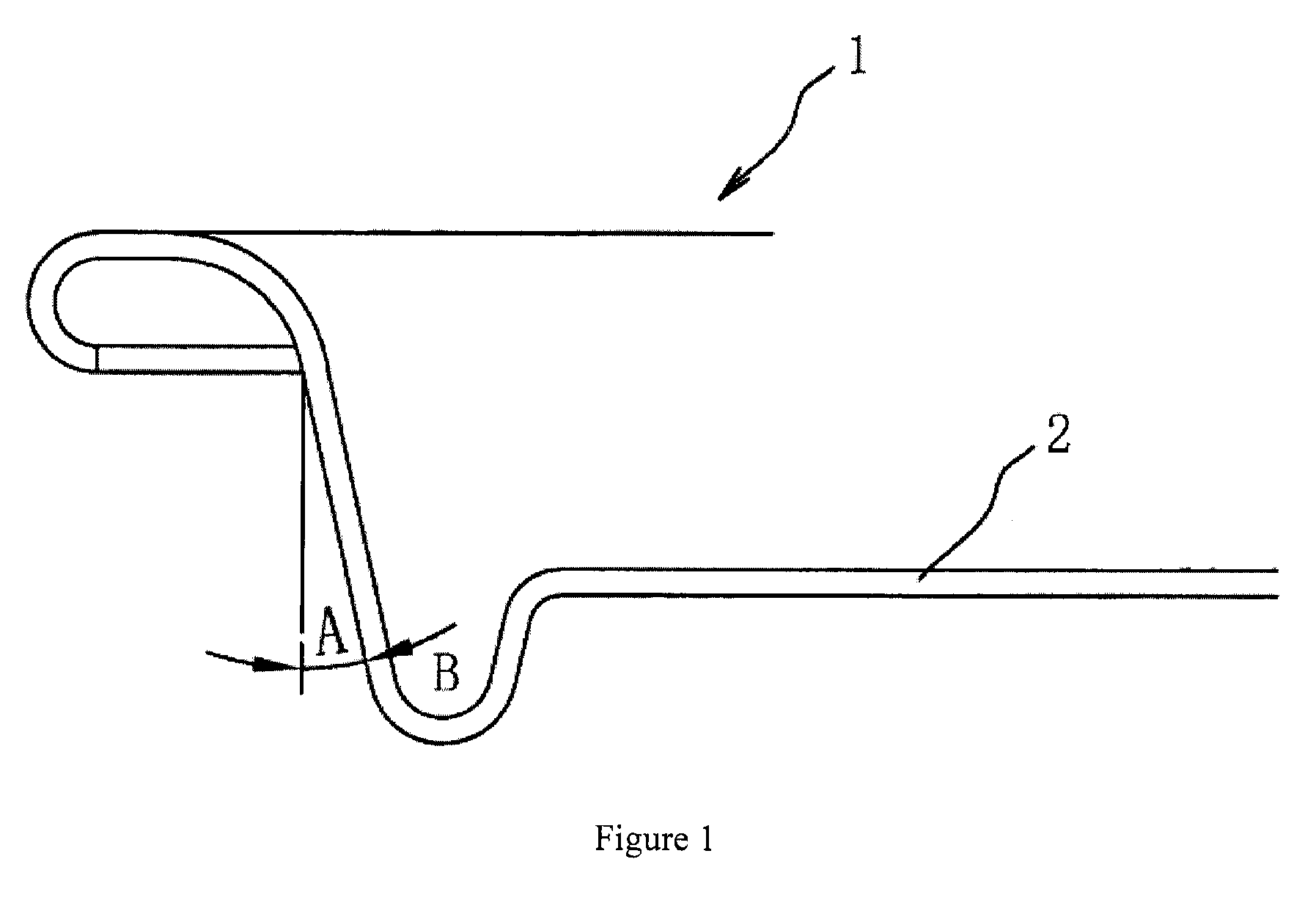
[0021]As shown in FIG. 1 and FIG. 2, an atmospheric pressure-resistant metal pop-top cover is constructed of two parts, the lid 1 and a pull-ring. The pull-ring is riveted onto the lid 1, and a concave countersink is established in the lid 1, beginning at its circumferential edge and extending toward its center. The center of the concave countersink is the circular convex platform 2, the angle of inclination A of the countersink is in the range of 15-45°, and the arc-shaped segments B1 and B2 in the bottom part of the convex platform and the corner portion of the rise segment C that rotate around the center of the lid are subjected to cold hardening treatment through forging and pressing.

[0022]The pop-top cover is completed by a major two-step production technology (the two large steps being categories of cold processing). The first step is to produce the base lid. Specifically, a coil material or a sheet material is fed in and the base lid is formed at one time by punch pressing an...

working example 2

[0024]As shown by reference to FIG. 1 and FIG. 3, an atmospheric-resistant metal pop-top cover is constructed of two parts, the lid 1 and a pull-ring. The differences from Working Example 1 are as follows: The convex platform is a two-step rising convex platform structure. That is, it is the two-step rising convex platform 3. The other factors are the same as in Working Example 1 and will not be described again here. As can be seen from FIG. 3, deformation and processing hardness could be achieved and the pressure resistance of the pop-top cover could be further increased using an embodiment in which the convex platform was the two-step rising convex platform 3.

[0025]The above-described working examples are intended to describe the technological concepts and characteristics of this invention, the objective being to allow those familiar with this technology to understand the content of this invention and to implement it on this basis. However, the scope of protection of this inventio...


PUM


Abstract

A gas pressure-resistant metal pop-top cover comprised of two parts, a lid (1) and a pull-ring, the pull-ring being riveted to the lid (1), there being a concave countersink that begins at the circumferential edge of the lid (1) and extends toward its center, and at the center of the concave countersink there being a round convex platform (2), wherein the angle of inclination A of the countersink is 15-60°, and the arc-shaped segments B1 and B2 of the bottom part of the convex platform and the corner portion of the rise segment C rotate around the center of the lid (1) and are subjected to cold hardening treatment through forging and pressing. Through a new design, the conflict between material-saving and maintaining pressure resistance in a pop-top cover has been solved, with the result that greater resistance to high pressure is provided as the notch diameter and thickness of materials in the pop-top cover are decreased.

Description

TECHNICAL FIELD[0001]The present invention relates to pop-top covers for food product and beverage cans; in particular, it relates to savings on materials and to an atmospheric pressure-resistant metal pop-top cover.BACKGROUND ART[0002]With the continuing increase in the living standards of the people, there is also an increasing demand on the market for foods and beverages, and the production of food and beverage cans has been growing each year. Severe competition in the metal packaging industry for food and beverages has arisen in this tide of economic development. For this reason, in order to conserve natural resources, lower costs and meet the demands of market competition, research on the saving of materials and the development of atmospheric pressure-resistant metal pop-top covers is not only a necessity for the survival and development of the industry, but it is also essential for the economic development of the market.[0003]At present, most of the metal beverage containers o...

Claims


Application Information

Patent Timeline
Patent Type & Authority Applications(United States)
IPC IPC(8): B65D17/34B21D51/44
CPCB65D17/163B21D51/44B65D17/4011
Inventor AN, SHU
Owner SUZHOU SLAC PRECISION EQUIP CO LTD
Learn More