Threaded joint for steel tubes

a technology for threaded joints and steel tubes, applied in the direction of drilling pipes, pipe elements, pipes, etc., can solve the problems of easy crevice corrosion and other problems, and achieve the effect of improving improving the operating efficiency, and increasing the galling resistance of the threaded join

Active Publication Date: 2010-03-11
VALLOUREC OIL & GAS FRANCE SAS +1
View PDF2 Cites 18 Cited by
  • Summary
  • Abstract
  • Description
  • Claims
  • Application Information

AI Technical Summary

Benefits of technology

[0024]At least one layer of a lubricating coating can be formed on the surface of the uppermost plating layer (the third plating layer when the upper third plating layer is formed or the first plating layer when it is not formed) to further increase the galling resistance of a threaded joint for steel tubes.
[0025]Such a lubricating coating is not always necessary in a threaded joint for steel tubes according to the present invention. This is particularly the case when a green dope is applied before makeup. However, when the material of the threaded joint is stainless steel or a high alloy steel which readily undergoes galling, by forming a lubricating coating as a top layer, the galling resistance of the threaded joint can be further improved, thereby making it possible to carry out makeup without application of a green dope, leading to improvement of the operating efficiency when assembling an oil country tubular good.
[0026]This lubricating coating can be one layer selected from a viscous liquid lubricating coating, a semisolid lubricating coating, and a solid lubricating coating. A viscous liquid lubricating coating and a semisolid lubricating coating have fluidity, so under high pressure conditions under which galling occurs, the lubricating components contained in the coating can be efficiently supplied into gaps between contact surfaces of a threaded joint by seepage, thereby exhibiting an especially high effect of preventing galling. The lubricating coating which is used is preferably one which contains substantially no heavy metal powder. A solid lubricating coating is preferably a coating comprising a suitable lubricating powder in an organic or inorganic binder matrix. The coating partly abrades under high surface pressure at the time of makeup or breakout, causing the l...

Problems solved by technology

As stated above, the Cu—Sn alloy plating layer proposed in Patent ...

Method used


Image

  • Threaded joint for steel tubes
  • Threaded joint for steel tubes

Examples


examples

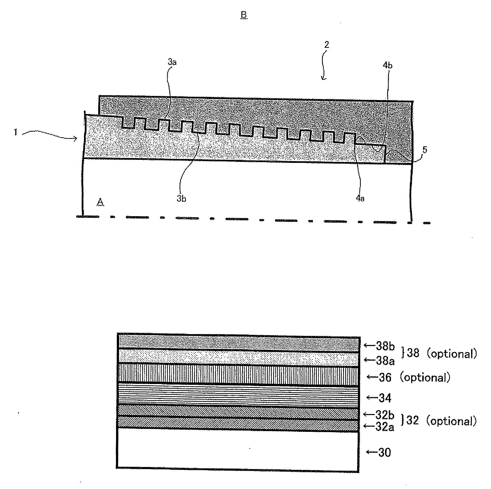
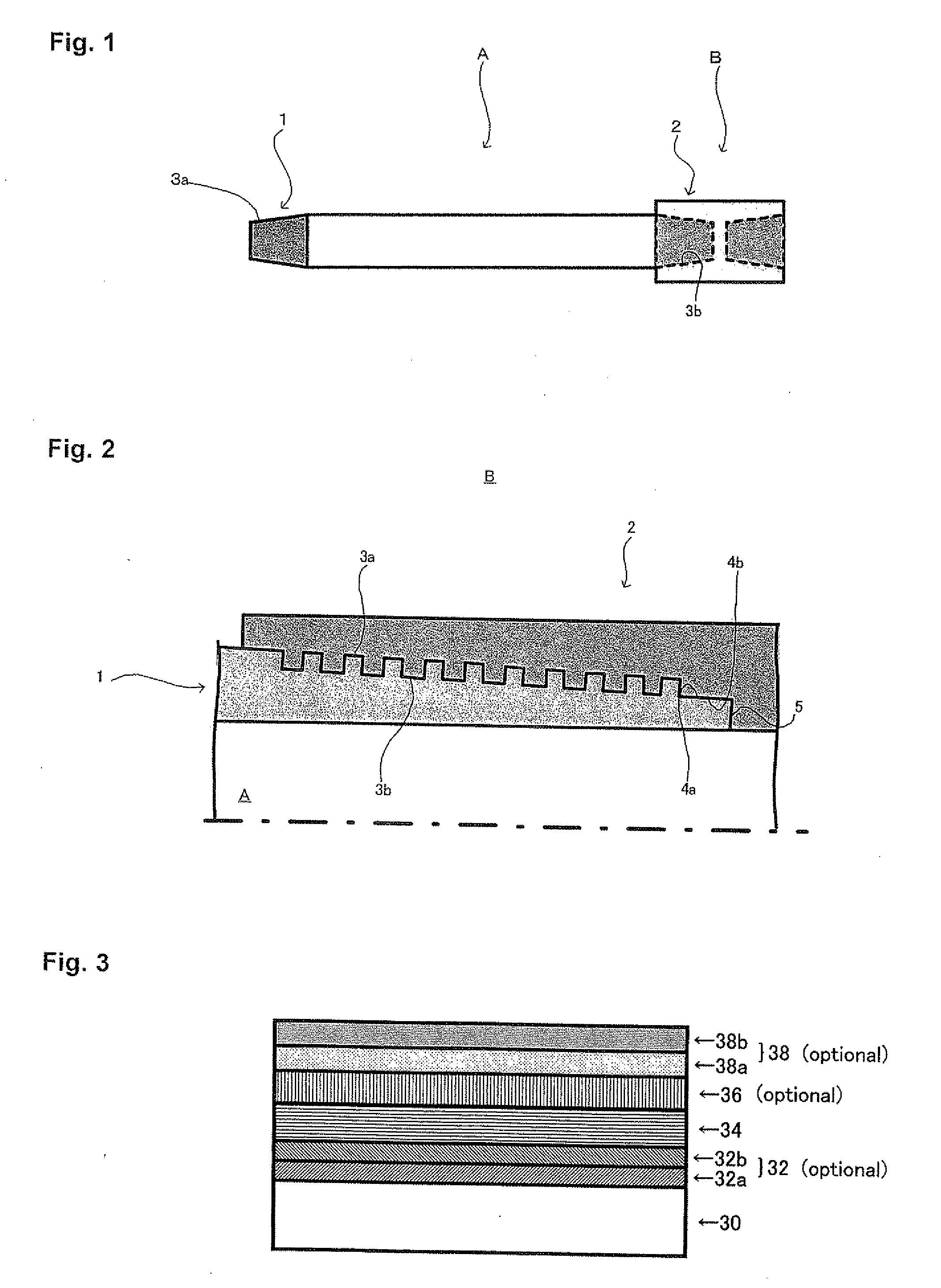
[0078]A large number of pins each having a male threaded portion and an unthreaded metal-to-metal contact portion (metal-to-metal seal portion) were formed by machining on both ends of seamless steel tubes having an outer diameter of 244.5 mm, a wall thickness of 13.84 mm, and a length of 1200 mm which were made from a 13% Cr steel (containing Ni and Mo), which is a high alloy steel. Correspondingly, a large number of boxes to which one of the pins could be connected and each of which has a female threaded portion and an unthreaded metal-to-metal contact portion were formed by machining on both sides of the inner surface of couplings made from the same steel.

[0079]The entire inner peripheral surface of each coupling including the contact surfaces of the box having the threaded portion and the unthreaded metal-to-metal contact portion was treated so as to form one or more layers of plating and optionally one or more layers of lubricating coating having the coating structure shown in ...


PUM

PropertyMeasurementUnit
Timeaaaaaaaaaa
Angleaaaaaaaaaa
Angleaaaaaaaaaa

Abstract

A pin-box type threaded joint for steel tubes having a contact surface (30) including a threaded portion and a nonthreaded metal-to-metal contact portion has improved leak resistance, galling resistance, and corrosion resistance particularly to crevice corrosion. The contact surface of at least one of the pin and the box is coated with a first plating layer (34) made of a Cu—Zn alloy or a Cu—Zn-M1 alloy (wherein M1 is at least one element selected from Sn, Bi, and In). Optionally, an undercoat (32) of one or both of a Ni plating layer (32a) and a Cu plating layer (32b) and an overcoat of a Sn-M2 alloy plating layer (36) (wherein M2 is one or more elements selected from Bi, In, Ni, Zn, and Cu) may be formed below and above the first layer, respectively. A solid lubricating coating (38a) and a viscous liquid or semisolid lubricating coating (38b) may also be formed atop the plating layer as a lubricating coating (38).

Description

TECHNICAL FIELD[0001]This invention relates to a threaded joint for steel tubes having improved galling resistance and corrosion resistance. A threaded joint for steel tubes according to the present invention is particularly suitable for use in connecting oil country tubular goods.BACKGROUND ART[0002]Oil country tubular goods (OCTG) which are driven into the ground for excavation of oil wells and natural gas wells can reach an overall length of several thousand meters in some cases. These long oil country tubular goods are constituted by steel tubes having a unit length of ten-some meters which are connected in series by short tubular couplings. The material of steel tubes and couplings is carbon steel, stainless steel, or high alloy steel, depending on the environment of use.[0003]These steel tubes are connected by threaded engagement of a pin having a male (external) threaded portion on its outer peripheral surface and a box having a female (internal) thread on its inner periphera...

Claims


Application Information

Patent Timeline
IPC IPC(8): F16L15/04
CPCC10M111/04C23C28/021C10M2201/0413C10M2201/0423C10M2203/1006C10M2205/143C10M2205/163C10M2209/1003C10M2219/046C10N2240/22C10N2250/14C10N2250/18C23C28/00C23C28/023C23C30/00C25D5/10C25D5/12C25D5/36C25D7/10E21B17/042F16L15/001F16L15/08F16L58/182C10M169/042C10N2210/02C10N2040/34C10N2050/023C10N2050/14C25D5/627C10N2010/04
Inventor KIMOTO, MASANARIGOTO, KUNIOTAKAHASHI, MASARUFUKUI, KUNIHIRONAGASAKU, SHIGEOIMAI, RYUICHIONISHI, SHIGEOIKEGAMI, HIROAKI
Owner VALLOUREC OIL & GAS FRANCE SAS
Why Eureka
Try Eureka