Method and device for performing optical suspension measurement

a technology of optical suspension and measurement method, applied in measurement devices, instruments, surveying and navigation, etc., can solve the problems of requiring additional effort and obstructing reliable measurement, and achieve the effect of measuring accuracy

Inactive Publication Date: 2010-03-11
ROBERT BOSCH GMBH
View PDF12 Cites 22 Cited by
  • Summary
  • Abstract
  • Description
  • Claims
  • Application Information

AI Technical Summary

Benefits of technology

[0010]This object is achieved via the features mentioned in claim 1 and claim 11. It is provided that the structured light is emitted by the illumination device in a narrow band in a specified narrow emission wavelength range, and the light is registered by the sensor unit, likewise in a narrow band, and in a receiving wavelength range that corresponds to the emission wavelength range, and it is evaluated in the evaluation device, wherein extraneous-light influences are removed. In the device, the object is attained by the fact that the illumination device is designed to generate narrowband light in a specified wavelength range, and the sensor unit for detecting the light in the narrow wavelength range includes an imaging lens system having at least one spectrally selective, optical element. Given these measures, the structured light pattern may be detected and evaluated in a reliable manner, even in unfavorable ambient light conditions, in particular in the presence of strong ambient light.
[0018]The measurement accuracy, in particular in cases in which an imaging lens system having a large angular aperture of the lens is used, is improved by the fact that, in the imaging lens system, the angle of the light that enters at a slant relative to the optical axis is reduced before it enters the at least one spectrally selective, optical element, and by the fact that the at least one spectrally selective, optical element (43) is situated within the imaging lens system at a point at which the angle of light that enters the imaging lens system at a slant relative to the optical axis is reduced. A similar influencing of the angle at which light enters the spectrally selective, optical element may also be brought about solely or in addition thereto via a curvature of the optical element.

Problems solved by technology

It is difficult, however, to obtain reliable measurement results with high precision using contactless optical methods of this type for measuring a chassis.
Although markings of this type for performing the measurement and evaluation serve as easily-detected structures on the wheel, they require additional effort to be realized.
In all of these contactless, optically measuring methods and devices, it is difficult without the use of special markings, and with the use of projected light to carry out exact, reliable, robust chassis measurements and / or dynamic tests of chassis components, in particular under raw, real measurement conditions, and with the requirement that the measurement be carried out in the simplest manner possible.

Method used


Image

  • Method and device for performing optical suspension measurement
  • Method and device for performing optical suspension measurement
  • Method and device for performing optical suspension measurement

Examples


Embodiment Construction

[0020]The present invention is explained in greater detail below using exemplary embodiments, with reference to the drawings.

[0021]FIG. 1 shows a schematic view of a measuring device in a measurement environment for measuring a chassis,

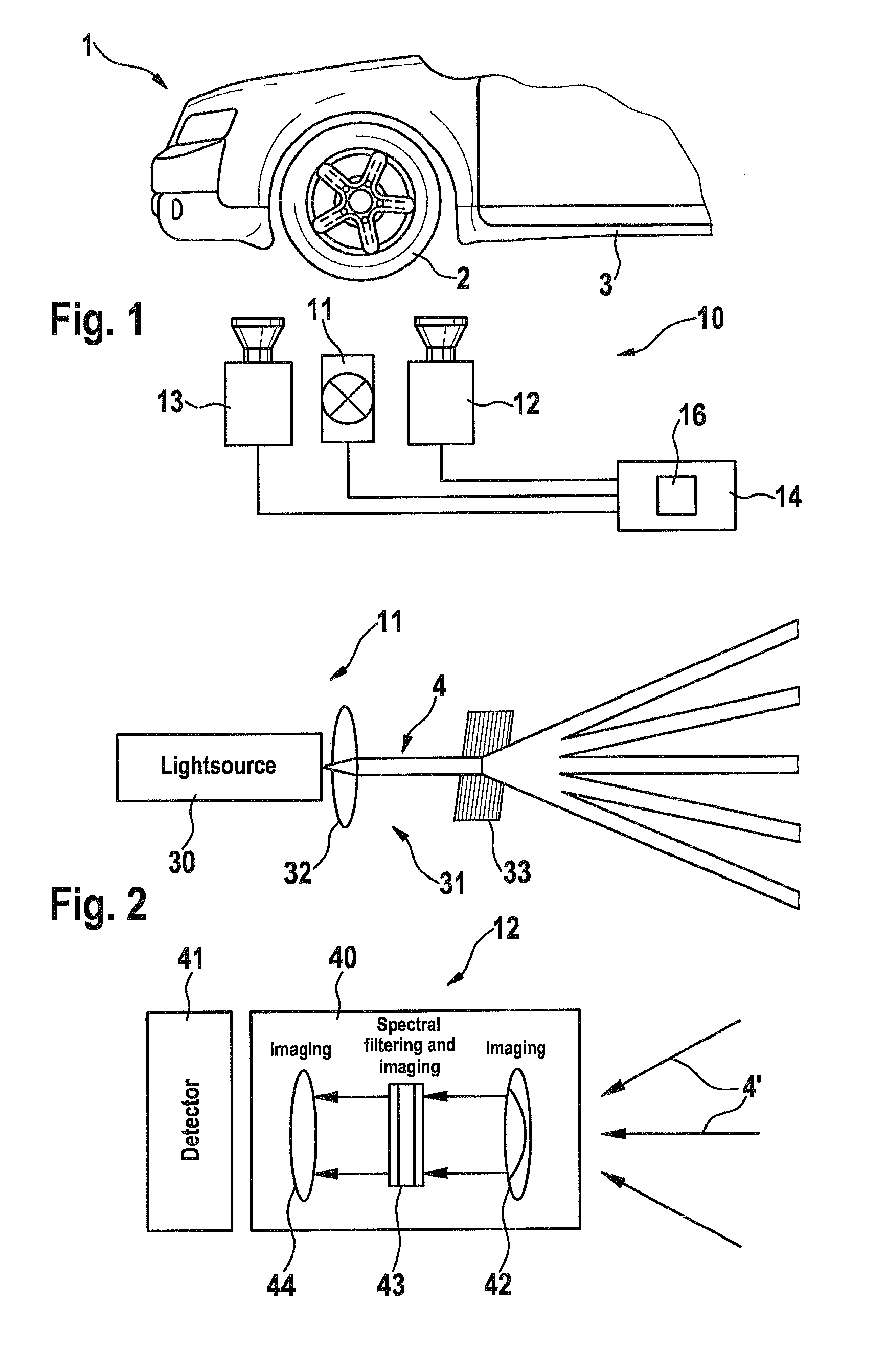
[0022]FIG. 2 is a schematic depiction of an illuminating device and a sensor unit, and

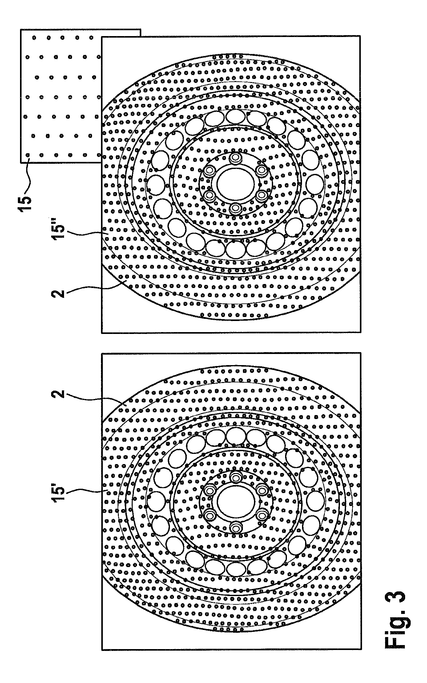
[0023]FIG. 3 shows a projected light pattern from the perspective of a left-hand image recording unit and a right-hand image recording unit of the sensor unit.

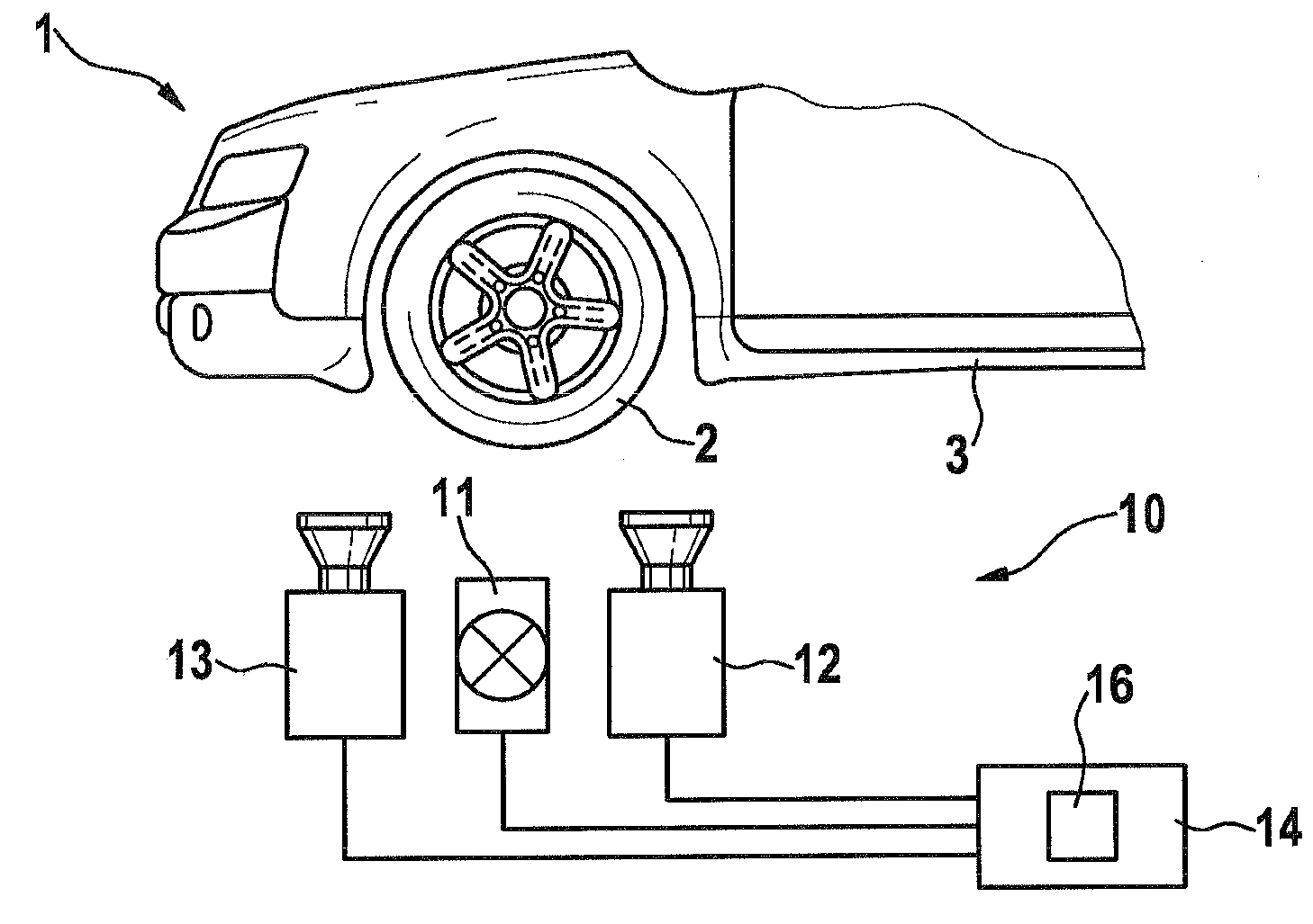
[0024]FIG. 1 shows a measurement environment for measuring a chassis, e.g. for determining the rotational axis of a vehicle wheel 2 according to a method that is described in greater detail in DE 10 2006 048 725.7, and a test set-up using a measuring device 10, wherein the vehicle may move past measuring device 10. In addition to wheel 2, body 3, preferably in the vicinity of wheel 2, may also be incorporated in the measurement.

[0025]Measuring device 10 includes a projection device 11 for light pattern 15, e.g....


PUM


Abstract

The invention relates to a method for optically measuring an undercarriage and / or for dynamically testing undercarriage components of a motor vehicle (1). At least one wheel (2) and / or at least one section of the vehicle (1) is illuminated with a light pattern (15) of structured light by means of an illumination device (11), and the reflected light (4′) is received by means of an imaging sensor unit (12, 13) and evaluated in an evaluation unit (16). The invention also relates to a device for carrying out the method. Even in suboptimal light conditions in the surrounding environments, a robust measurement is achieved because the structured light is emitted by the illumination device in a narrow band in a specified narrow emission wavelength range, and because the light is likewise detected by means of the sensor unit (12, 13) in a receiving wavelength range corresponding to the emission wavelength range and is evaluated in the evaluation unit (16), wherein foreign light influences are removed.

Description

BACKGROUND INFORMATION[0001]The present invention relates to a method for measuring a chassis and / or for dynamically testing chassis components of a motor vehicle, in which at least one wheel and / or at least one section of the vehicle is illuminated via an illumination device using a pattern of structured light, and in which the reflected light is recorded via an imaging sensor unit and is evaluated in an evaluation device. The present invention also relates to a device for carrying out the method.[0002]A method and a device of this type are described in DE 103 35 829 A1 and the parallel publication EP 1 505 367 A2. In this known method for determining axle geometry, a light pattern, such as a pattern of strips having a varying periodicity, monochromatic grid structures, or flat coding in the form of color coding is projected onto the end face of the wheel, and the light that is reflected by the end face of the wheel is received by an image converter from a direction that is differe...

Claims


Application Information

Patent Timeline
Patent Type & Authority Applications(United States)
IPC IPC(8): G01B5/00G01B11/26
CPCG01B11/2755G01B2210/14G01B2210/286G01B2210/20G01B2210/146
Inventor NOBIS, GUENTERABRAHAM, STEFFENSCHMIDTKE, BERNDKNOLL, CHRISTIANKALLMANN, ULRICH
Owner ROBERT BOSCH GMBH
Why Eureka
Try Eureka