System, apparatus and method for extracting image cross-sections of an object from received electromagnetic radiation

Active Publication Date: 2010-03-11
CELLOPTIC
View PDF5 Cites 40 Cited by
  • Summary
  • Abstract
  • Description
  • Claims
  • Application Information

AI Technical Summary

Benefits of technology

[0031]Another object of this invention is to provide a novel apparatus, wherein a predetermined thickness and coefficients of absorption or reflectance of the electromagnetic radiation assembly is configured to control the phase and intensity of the diffracted light.
[0032]Another object o

Problems solved by technology

However, conventional techniques may disadvantageously require an active illumination source, or place limitations on a light source (e.g., may require coherent light, a point light source or a bandwidth limited light), place limitations on movement of the object or the sensing apparatus (e.g., require th

Method used


Image

  • System, apparatus and method for extracting image cross-sections of an object from received electromagnetic radiation
  • System, apparatus and method for extracting image cross-sections of an object from received electromagnetic radiation
  • System, apparatus and method for extracting image cross-sections of an object from received electromagnetic radiation

Examples


first embodiment

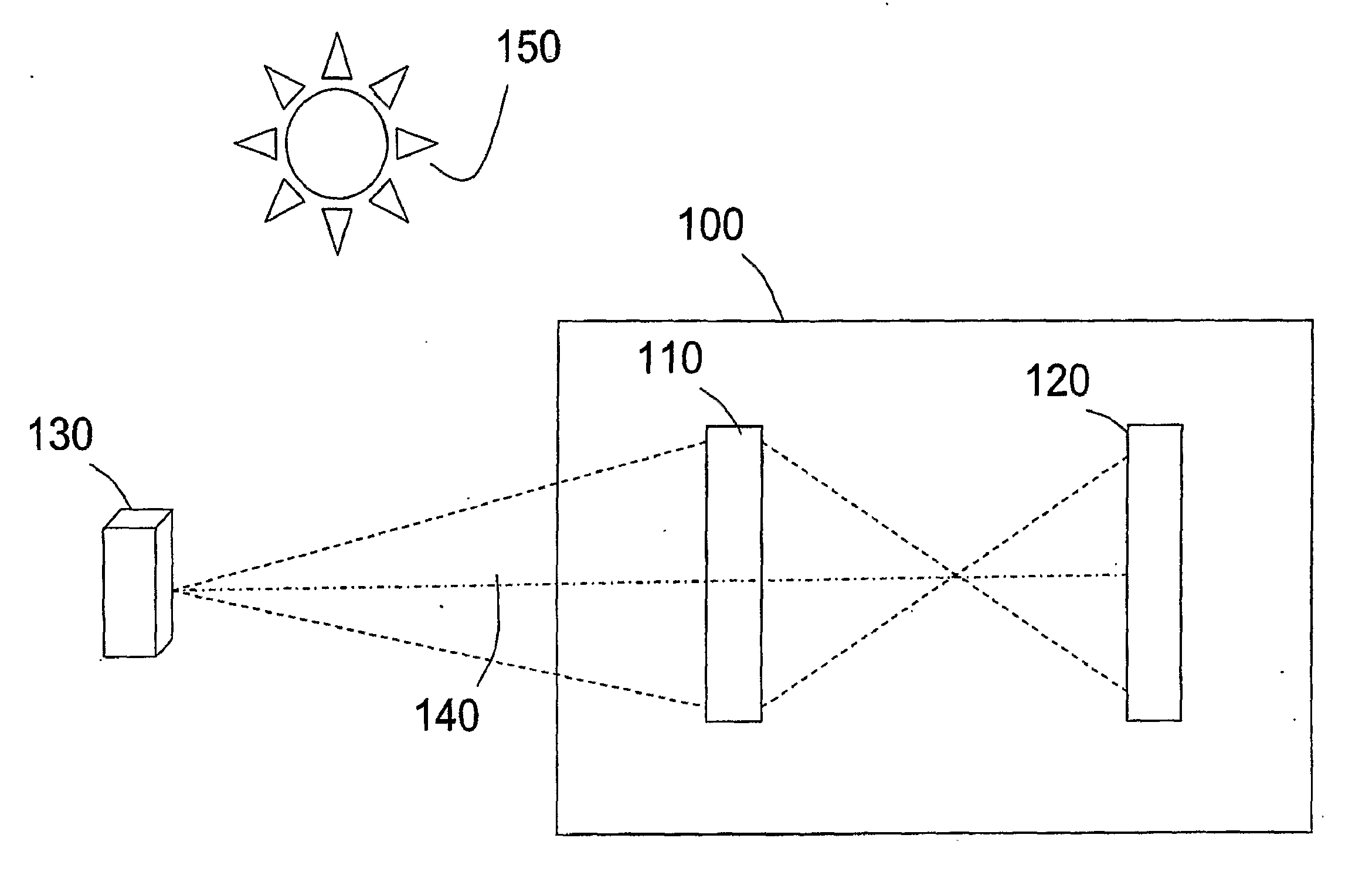
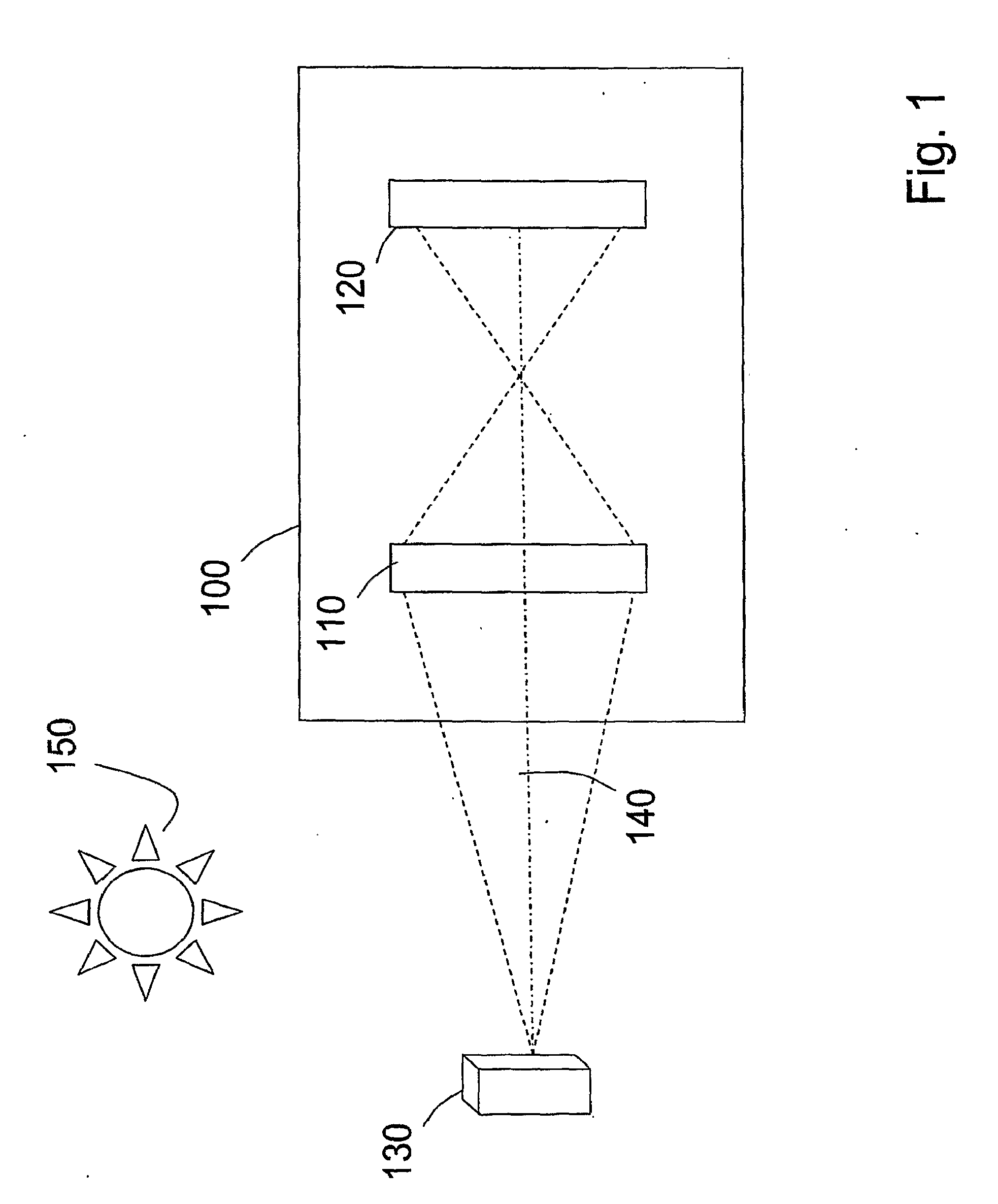
[0153]FIG. 1 is a block diagram of an optical apparatus 100 according to the present invention. The optical apparatus 100 is configured to capture a three-dimensional information of an object 130, and the optical apparatus 100 includes an optical assembly 110 and an image capture assembly 120. In particular, the optical assembly 110 receives light from the object 130 along a receiving optical axis 140. For example, the optical assembly may receive light from the sun 150 that is reflected or scattered by reflecting surfaces on the object 130. The received light may be polychromatic and incoherent light, such as reflected sunlight. In addition, the light from the object may be fluorescent light or chemiluminescent light emitted by the object. The optical apparatus 100, in this embodiment, does not illuminate the object but passively receives light from the object.

[0154]The optical assembly 110 transforms the received light according to a transformation described below, and transmits t...

fourth embodiment

[0271]FIG. 27D is a block diagram of an apparatus configured to capture different cross sections of an object 130, without moving either the object 130 or the apparatus 1400. In this embodiment, the effective focal length of the correlator's input lens 302 is varied using an electrically controlled diffractive lens (ECDL) 2718, which may be implemented using a SLM. Alternatively, lens 302 may be replaced by the ECDL 2718. In this embodiment, holograms may be captured using various focal lengths of the correlator's input lens or ECDL, with each hologram corresponding to a different cross-section.

[0272]Although different cross-sections may be obtained by changing the input plane of the object or the input focal plane, different cross-sections may alternatively be obtained by changing a location of the output plane.

fifth embodiment

[0273]FIG. 28A is a schematic and block diagram of an apparatus configured to capture different cross sections of an object 130, by moving a location of image capture assembly 1406 with respect to incoherent correlator 1402. In this example, a motor 2806 controls a movable platform 2802, using gear 2804. The platform 2802 is configured to move image capture assembly 1406 along axis 2808. Plural holograms corresponding to plural cross-sections may be obtained at each different position of image capture assembly 1406 along axis 2808.


PUM


Abstract

An Apparatus and method to produce a hologram of a cross-section of an object includes an electromagnetic radiation assembly configured to receive a received electromagnetic radiation, such as light, from the object. The electromagnetic radiation assembly is further configured to diffract the received electromagnetic radiation and transmit a diffracted electromagnetic radiation An image capture assembly is configure to capture an image of the diffracted electromagnetic radiation and produce the hologram of the cross-section of the object from the captured image. The hologram of the cross-section includes information regarding a single cross-section of the object.

Description

CROSS-REFERENCE TO A RELATED APPLICATION[0001]This application is related to International Patent Application No. PCT / US2006 / 027727 filed Jul. 18, 2006, which is incorporated herein by reference in its entirety.BACKGROUND OF THE INVENTION[0002]1. Field of the Invention[0003]This invention relates to an apparatus for capturing electromagnetic radiation, such as light or other forms of electromagnetic radiation, from an object and extracting object geometric information from the received radiation, in the field of three-dimensional imaging and holography. The invention also relates to a system and method of performing those functions.[0004]2. Discussion of the Background[0005]Conventional techniques for capturing three-dimensional information from physical objects include holography, range-finding, and tomography. However, conventional techniques may disadvantageously require an active illumination source, or place limitations on a light source (e.g., may require coherent light, a poi...

Claims


Application Information

Patent Timeline
IPC IPC(8): G03H1/16G03H1/00
CPCG03H1/0005G03H1/06G03H1/08G03H2226/11G03H2001/0033G03H1/0443G03H2001/0452G03H1/041G03H1/26G03H5/00G03H2210/33G03H2223/23
Inventor ROSEN, JOSEPH
Owner CELLOPTIC
Why Eureka
Try Eureka