Compact fiber optic sensors and method of making same

a technology of fiber optic sensors and fiber optic grating, which is applied in the direction of cladding optical fibre, instruments, heat measurement, etc., can solve the problems of fbg temperature calibration and even repeatability, significant and adversely affecting the accuracy of fbg, and preventing fiber breakage. , the effect of slow cooling the bend

Active Publication Date: 2010-03-11
KYTON
View PDF33 Cites 39 Cited by
  • Summary
  • Abstract
  • Description
  • Claims
  • Application Information

AI Technical Summary

Benefits of technology

[0014]The exemplary illustrative technology herein provides compact, optically double-ended sensor probes with at least one substantially 180° bend provided in the optical fiber in close proximity to an FBG sensor. This example non-limiting structure may include for example all versions of at least net 180° bends in definition and bends of somewhat less than 180° that would lead to slightly divergent input and output fibers but still allow a physically single-ended probe configuration within a desired maximum diameter. Further, the FBG sensor can in example non-limiting implementations be suspended in the probe in such a way that the expansion and contraction of the probe casing will not materially influence the temperature reading of the FBG by adding time-or-temperature varying stress components to the FBG. Such time-dependent drift mechanisms that can be avoided include creep in reading (at a constant temperature) that frequently occurs when attempts are made to fasten fibers incorporating FBGs at both ends of the FBG to the casing in a direction substantially on a line with each other, even if said fiber is bent somewhat (substantially less than) 180°) to prevent fiber breakage.
[0015]Mechanical 180° bends can be mechanically restrained to force them into a compact form factor if means are employed to prevent such restraints from themselves causing variations in the calibration of the sensors with time and temperature cycling. Thermally formed bends can be made by heating the fiber beyond its softening point utilizing any of the methods of, but not exclusively confined to, a flame, an oven, a hot filament, a glow bar, or a laser, for instance a CO2 laser. The buffer coatings can be removed before heating, burned off during the bending operation or, if an inert atmosphere is employed, an adherent, protective carbon layer can be left on the fiber bend. Reliability of the bend can be enhanced by annealing and slow cooling the bend. Since FBGs in many fibers can be erased by high temperature, the FBG can be of a type that can withstand the temperature of the bending operation, it can be written into the fiber before bending and kept a safe distance away from the bend or the fiber can be loaded with hydrogen after the bending operation and the grating can be written into the bent fiber after the hydrogen loading step.

Problems solved by technology

Advantages of optical sensors over electronic sensors are generally well known, in spite of their present overall greater cost (including the sensor readers).
These properties generally cause difficulty if the sensor is to be used over a very wide temperature range, if their temperature sensitivities or temperature ranges need to be enhanced beyond that of the simple buffered fiber (by attachment to a material of a higher expansion coefficient), if they will be subjected to rough handling, or firmly mounted to dissimilar materials (to enhance thermal equilibrium with the object to be measured).
In addition, fabrication difficulties increase when the effects of strain are to be separated unambiguously from those of temperature and when the sensor is made compact enough to compete with existing electronic sensors in form factor while still maintaining their ability to be multiplexed.
If a section of optical fiber containing an FBG is attached to another object or material (substrate) with adhesive or even thermal grease, the FBG's temperature calibration and even repeatability is significantly and usually adversely affected by all the components of the attachment system, especially over a temperature range of tens or hundreds of degrees Celsius, because of the strain sensitivity of the FBG.
In addition, the viscous material itself is often not stable under thermal cycling, especially if it is a glass with a low melting point or is a polymer and its glass transition temperature is exceeded.
This data does not address concerns with the well-known increased static fatigue failure of optical fiber as the bend radius decreases below about 3 mm; it is an illustrative example only of the optical power loss due to the bend.
In general use, a fiber optic sensor package with a width or diameter of 20-30 mm or greater is highly undesirable.

Method used


Image

  • Compact fiber optic sensors and method of making same
  • Compact fiber optic sensors and method of making same
  • Compact fiber optic sensors and method of making same

Examples


Embodiment Construction

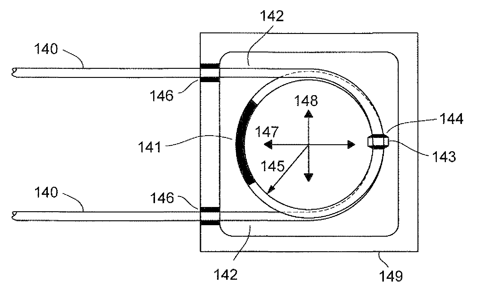
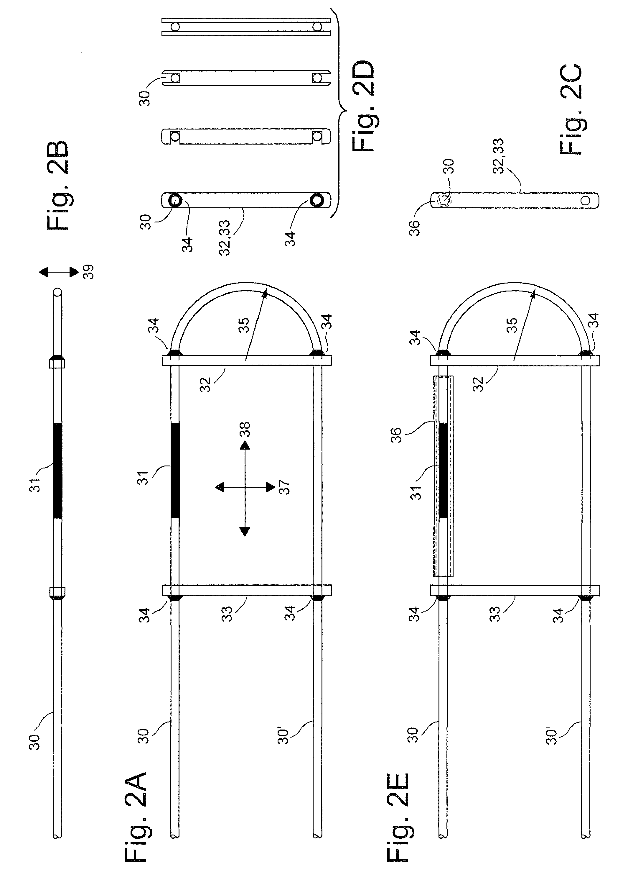
[0063]FIGS. 2A-2E show different views of one example illustrative non-limiting example implementation providing a competitively small, physically single ended and yet optically double ended, strain-free temperature sensor probe. In FIG. 2A, the input / output fibers 30, 30′ shown have numerical aperture greater than 0.15 and a 180° uniform mechanical or thermal bend with uniform radius 35 less than or equal to 10 mm. At least one front brace 32 is provided with its centerline substantially along the diameter of the bend 35 and at least one back brace 33 fixed to the fiber at least at points 34 with a fixative. The purpose of said braces 32, 33 to maintain the at least one FBG 31 free of longitudinal and / or bending stresses, while being of low enough mass to prevent the fiber from bending substantially in the direction normal to the plane of the 180° bend under gravity or other forces. While said braces 32 and 33 may be of different materials, it is preferable that they be of the same...


PUM

PropertyMeasurementUnit
bend angleaaaaaaaaaa
distanceaaaaaaaaaa
weightaaaaaaaaaa

Abstract

A compact, optically double-ended sensor probes with at least one 180° bend provided in the optical fiber in close proximity to a fiber Bragg grating temperature sensor suspends the optical fiber within a casing in such a way that the expansion and contract of the probe casing will not materially influence the temperature reading of the fiber Bragg grating by adding time varying or temperature varying stress components.

Description

CROSS-REFERENCE TO RELATED APPLICATION[0001]This application claims the benefit of priority from provisional application No. 61 / 095,885 filed Sep. 10, 2008, the contents of which are incorporated herein by reference.STATEMENT REGARDING FEDERALLY SPONSORED RESEARCH OR DEVELOPMENT[0002]N / AFIELD[0003]The technology herein relates to fiber Bragg grating optical temperature sensors fabricated in the cores of high-silica optical fibers, and to techniques for making such sensors compact enough in form factor to compete economically with, and be used physically in place of, common small electronic sensors in various applications while preserving their advantages in multiplexing on a single fiber.BACKGROUND AND SUMMARY[0004]Many or most single mode communications-grade optical fibers and many multi-mode fibers are fabricated from high-silica glass components. Such fibers have a high Young's Modulus, and are termed nearly “perfectly elastic” in addition to possessing very low thermal coeffici...

Claims


Application Information

Patent Timeline
Patent Type & Authority Applications(United States)
IPC IPC(8): G02B6/00G02B6/42G02B6/34B29D11/00
CPCB29D11/00663G02B6/02209G02B6/0218G01K11/3206
Inventor SWINEHART, PHILIP R.MAKLAD, MOKHTAR M.
Owner KYTON
Why Eureka
Try Eureka