Brake Control System

a technology of control apparatus and brake, which is applied in the direction of braking system, motor/generator/converter stopper, dynamo-electric converter control, etc., can solve the problems of preventing automatic transmission vehicles from using residual braking force, and depressing action may accelerate vehicles, so as to reduce wasteful electric-power consumption and heat generation

Active Publication Date: 2010-03-11
HITACHI ASTEMO LTD
View PDF4 Cites 40 Cited by
  • Summary
  • Abstract
  • Description
  • Claims
  • Application Information

AI Technical Summary

Benefits of technology

[0011]According to the aspect of the invention, the brake control apparatus for a vehicle can achieve a reduction in the wasteful electric-power consumption and heat generation while the vehicle is not moving. In addition, the b

Problems solved by technology

This configuration brings about a problem that the residual braking force prevents an automatic transmission vehicle from starting smoothly creeping forward in a heavy traffic.
To put it differently, the problem i

Method used


Image

  • Brake Control System
  • Brake Control System
  • Brake Control System

Examples


first embodiment

of Brake Control System

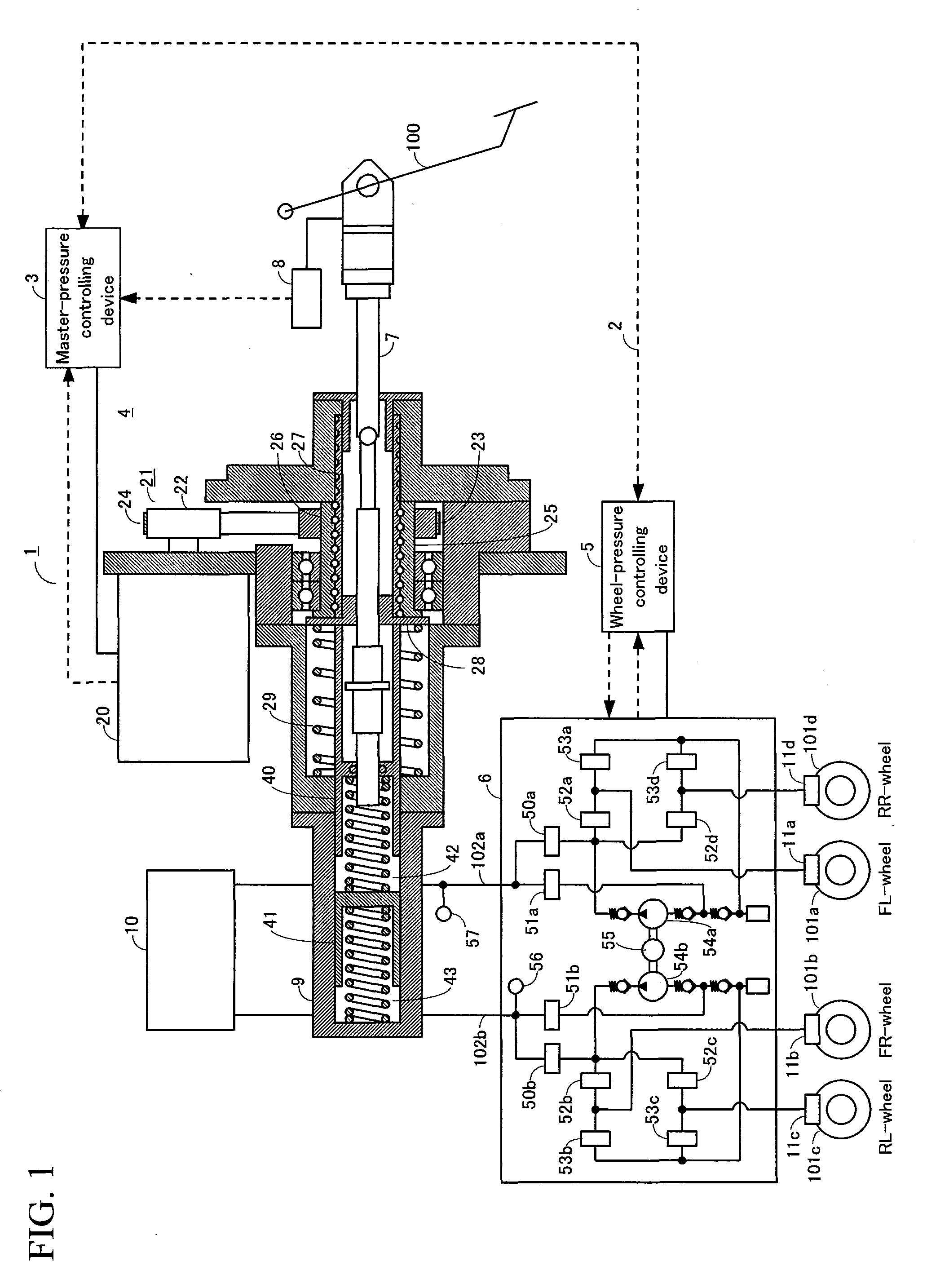
[0031]A first embodiment of a brake control system will be described below. FIG. 1 illustrates an overall configuration of the brake control apparatus. In FIG. 1, the arrowed dash lines represent signal lines, and the arrows indicate the direction in which their respective signals flow.

[0032]A brake control system 1 includes a master-cylinder pressure controlling device 3, master-cylinder pressure controlling mechanism 4, a wheel-cylinder pressure controlling device 5, a wheel-cylinder pressure controlling mechanism 6, an input rod 7, a braking operation amount detecting device 8, a master-cylinder 9, a reservoir tank 10, and wheel-cylinders 11a to 11d. A first pressurizing-depressurizing unit includes a brake pedal 100 and the input rod 7 whereas a second pressurizing-depressurizing unit includes the master-cylinder pressure controlling device 3, the master-cylinder pressure controlling mechanism 4, and a primary piston 40.

[0033]Two-way communications are all...

second embodiment

of Brake Control System

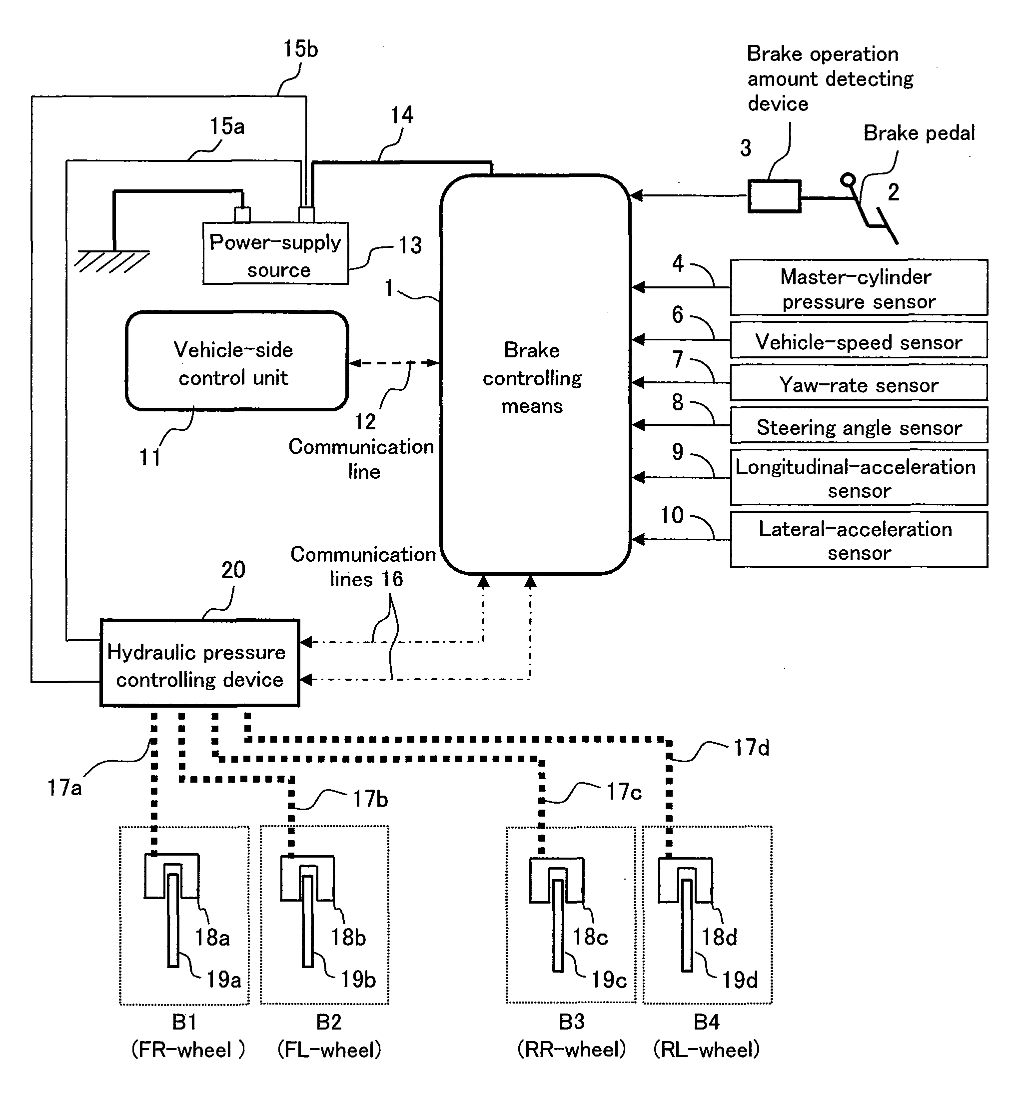
[0069]A second embodiment of the electric hydraulic brake control system for a vehicle of the present invention will be described by referring to FIGS. 3 to 5. FIG. 3 illustrates a system configuration of the electric hydraulic-brake control system including a means 1 for controlling brakes, a hydraulic-pressure controlling device 20, and signal lines (communication lines) and electric-power lines that connect the above-mentioned members.

[0070]The means 1 for controlling brakes receives various kinds of sensor information transmitted from such sensors as: a braking operation amount detecting device 3 to detect the amount of the driver's operation on a brake pedal 2; a master-cylinder pressure sensor 4; vehicle-speed sensors 6 to detect the speed of their respective wheels of the vehicle (i.e., the speed of each of the four wheels in total—a right-and-left pair of front wheels and a right-and-left pair of rear wheels); a yaw-rate sensor 7 to detect the yaw rate...

third embodiment

of Brake Control System

[0088]Next, a third embodiment of the brake control system will be described. The system of the third embodiment has a configuration that is basically the same as that of the second embodiment, except for the configuration of the source of hydraulic pressure.

[0089]FIG. 6 schematically illustrates a hydraulic circuit of the brake control system according to the third embodiment. Firstly, the configuration of the hydraulic circuit will be described. The master-cylinder 41 is what is known as a tandem-type cylinder. The master-cylinder 41 is capable of supplying the same hydraulic pressure independently to the P system that reaches the wheels via the oil passage 31a, and the S system that reaches the wheels via the oil passage 31b. The reservoir 43 for storing the brake fluid is connected to the master-cylinder 41.

[0090]The wheel-cylinder 18a of the FL-wheel and the wheel-cylinder 18b of the FR-wheel are connected respectively to the oil passage 31a of the P-syst...


PUM


Abstract

Provided is a brake control apparatus for a vehicle which detects an amount of brake-pedal operation by means of an electric signal, and then calculates a braking force demanded by a driver from the electric signal, and thereby generates the demanded braking force. A control mode for a braking force is switched from a normal control mode to a stationary-vehicle control mode, if a determination that the vehicle is in a stationary state is followed by another determination that an electric signal corresponding to an actual braking force exceeds a command value for a stationary-vehicle braking force while the vehicle is in the stationary state. The control mode for a braking force is switched from the stationary-vehicle control mode to the normal control mode, if it is determined that the demanded braking force becomes smaller than the command value for the stationary-vehicle braking force. In addition, in the stationary-vehicle control mode, a braking force generated by a means for braking is equal to the command value for the stationary-vehicle braking force, whereas, in the normal control mode, the braking force generated by the means for braking is equal to the braking force demanded by the driver.

Description

BACKGROUND OF THE INVENTION[0001]1. Field of the Invention[0002]The invention relates to a brake control apparatus of a vehicle, and more particularly to a brake control apparatus of a vehicle to electrically control either the electric power or the hydraulic pressure by detecting the amount of brake-pedal operation by means of electric signals, and thus to generate either a braking force or an assisting force corresponding to the amount of brake-pedal operation.[0003]2. Description of the Related Art[0004]In recent years, a variety of brake control apparatuses have been studied in which a braking force demanded by the driver is calculated from electric signals corresponding to the amount of the driver's depressing amount of a brake pedal, and the demanded braking force is generated through electrical control. One of the problems that are common to all these brake control apparatuses is that, when the driver demands, while the vehicle is not moving, a braking force that is larger th...

Claims


Application Information

Patent Timeline
IPC IPC(8): H02P15/00B60T7/12
CPCB60T8/4872Y10T477/393B60T8/4081Y10T477/80B60T7/042B60T8/3255B60T1/10B60T7/22
Inventor NISHINO, KIMIOINNAMI, TOSHIYUKIMATSUZAKI, NORIKAZUNASU, SHINGOMIYAJIMA, AYUMA
Owner HITACHI ASTEMO LTD
Why Eureka
Try Eureka