Force-sensing catheter with bonded center strut

a force-sensing catheter and center strut technology, applied in the field of medical devices, can solve the problems of not providing a means for accurately providing force sensing and no teaching with respect to sensing force at the tip of the catheter

Active Publication Date: 2010-03-11
BIOSENSE WEBSTER INC
View PDF105 Cites 177 Cited by
  • Summary
  • Abstract
  • Description
  • Claims
  • Application Information

AI Technical Summary

Benefits of technology

[0020]The distal end of the center strut comprises at least one snap-fit notch and the molded coupling further comprises at least one snap-fit wedge ada

Problems solved by technology

While this patent discusses the use of such sensors for measuring and depicting the bend of the catheter to the user it does not provide a means for accurately providing force sensing at the tip of the catheter.
U.S. Pat. No. 6,612,992 to Rambow et al. discloses an ultrasoun

Method used


Image

  • Force-sensing catheter with  bonded center strut
  • Force-sensing catheter with  bonded center strut
  • Force-sensing catheter with  bonded center strut

Examples


Embodiment Construction

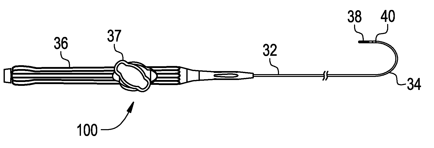
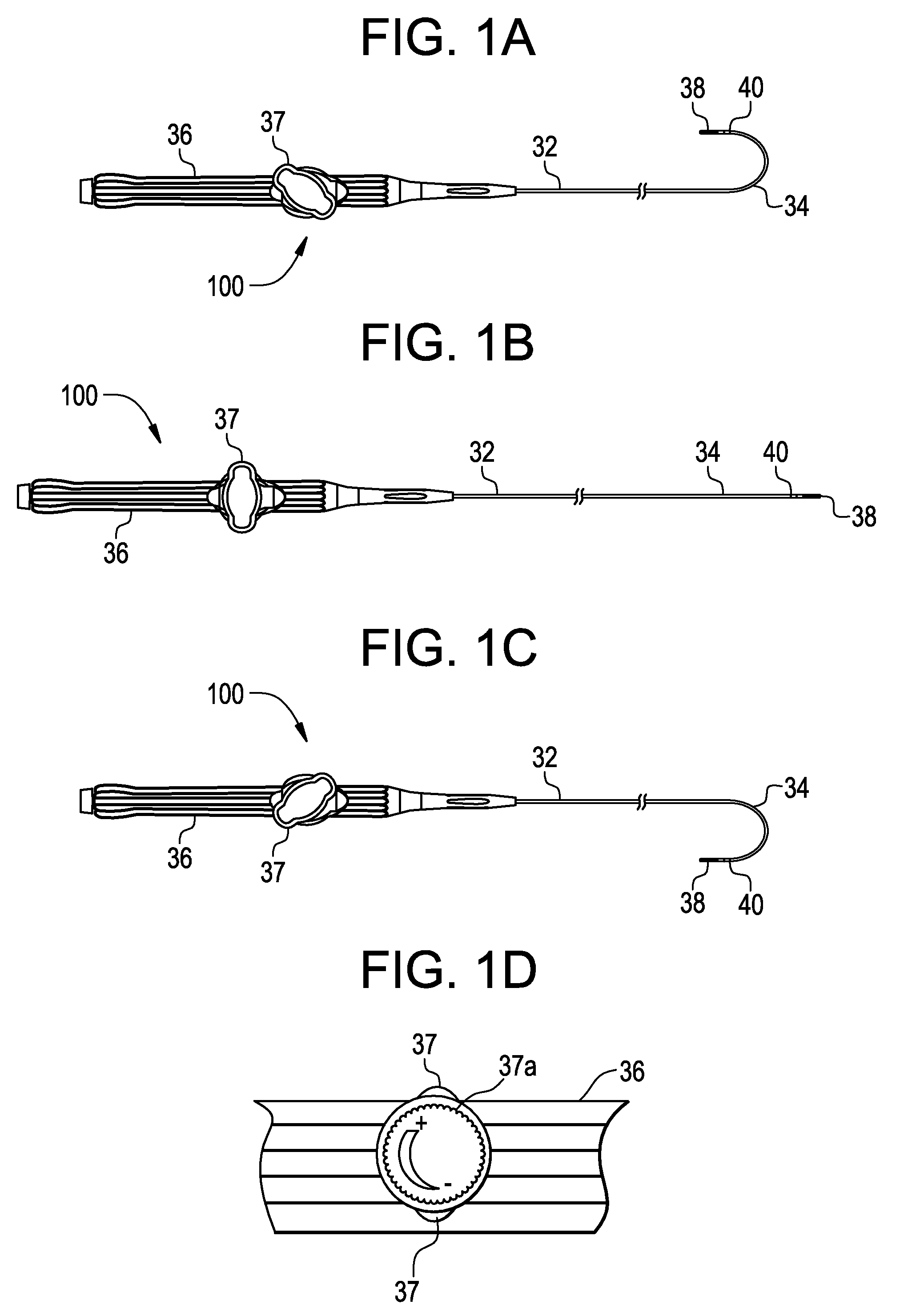
[0038]FIGS. 1A-C depict a planar view of an embodiment of a deflectable catheter in accordance with the present invention. As shown in FIG. 1B, a preferred catheter 100 comprises an elongated tubular catheter body having a proximal section 32, a distal tip section 34 and a control handle 36 at the proximal end of the proximal section 32. Tip electrode 38 and optional ring electrode 40 are placed at or near deflectable distal tip section 34 so as to provide a source of ablation energy if the desired device is an RF ablation catheter or for receiving electrical signals if the catheter is a diagnostic EP mapping catheter. Control handle 36 may be one of many designs capable of placing a pulling force on puller wires used to deflect the deflectable tip section 34. Preferably, control handle 36 is the handle used in the Biosense EZ-Steer bidirectional family of products which control handle is depicted in FIGS. 1A-C. The “rocker” type lever 37 pulls one of two puller wires to deflect the...


PUM


Abstract

A force-sensing catheter for diagnosing or treating the vessels found within a body or body space includes a center strut that is bonded, preferably thermally, along its longitudinal axis with the thermoplastic tubular member within which it is housed. The tubular member preferably has three layers: an inner layer, a braided layer and an outer layer. One or more semiconductor or metallic foil strain gages are affixed to the center strut in order to provide a measure of the bending and torsional forces on the distal tip of the catheter. Temperature compensation is achieved by having a temperature sensor near the strain gages and calibrating the catheter over a range of temperatures.

Description

FIELD OF THE INVENTION[0001]The present invention relates to a medical device for use in the vessel of a patient for the purpose of diagnosing or treating the patient, such as mapping tissue and / or ablating tissue using radio frequency (RF) or other sources of energy. More particularly, the invention relates to a catheter having a center strut bonded into the catheter tip to define an inseparable composite tip structure that maximizes the open internal volume of the catheter tip and the torsional rigidity of the catheter tip while minimizing the outside diameter of the catheter tip and providing uniform on-plane tip deflection. On the bonded center strut one or more strain gage force sensors are affixed for measuring catheter tip deflection and tip axial and side forces. The catheter may also include puller wires for deflecting the tip portion of the catheter.BACKGROUND OF THE INVENTION[0002]Many abnormal medical conditions in humans and other mammals have been associated with disea...

Claims


Application Information

Patent Timeline
IPC IPC(8): A61M25/00A61M39/10A61B5/103
CPCA61B5/042A61B18/1492A61B19/5244A61B2017/003A61B2019/464A61B2218/002A61B2562/0261A61B2562/0247A61M25/0136A61M25/0141A61M25/0144A61M25/0147A61M2025/015A61B2560/0252A61B34/20A61B2090/064A61B5/283
Inventor SELKEE, THOMAS VAINO
Owner BIOSENSE WEBSTER INC
Why Eureka
Try Eureka