Laminoplasty implant

Inactive Publication Date: 2010-03-11
BLUE FURY CONSULTING
View PDF3 Cites 19 Cited by
  • Summary
  • Abstract
  • Description
  • Claims
  • Application Information

AI Technical Summary

Benefits of technology

[0006]The present invention provides a laminoplasty device, implant, or plate is hollow to provide a lattice for fusion of the lamina. The device includes fixation screw holes enabling the system to be inserted and fixed in the laminar defect similar to current laminoplasty plates. The

Problems solved by technology

The constriction of the spinal cord in the cervical spine often produces pain, weakness, or loss of feeling in extremities.
Other causes for narrowing of the spinal canal include disc shrinkage, which causes the disc space to narrow and the annulus to bulge and mushroom out, resulting in pressure on the spinal cord.
Degenerative arthritis of facet joints can cause joints to enlarge, or the vertebra to slip with respect to each other, also compressing the spinal cord.
A limitation of the laminectomy procedure is that it involves removal of the supporting structures at the back of the vertebrae which align the spinal column.
The result may be that a patient suffers some postural deformity.
Many of the curr

Method used


Image

  • Laminoplasty implant
  • Laminoplasty implant
  • Laminoplasty implant

Examples


Example

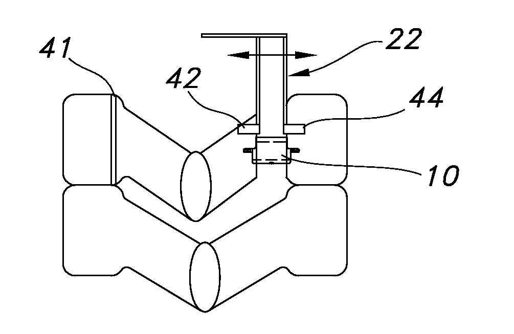
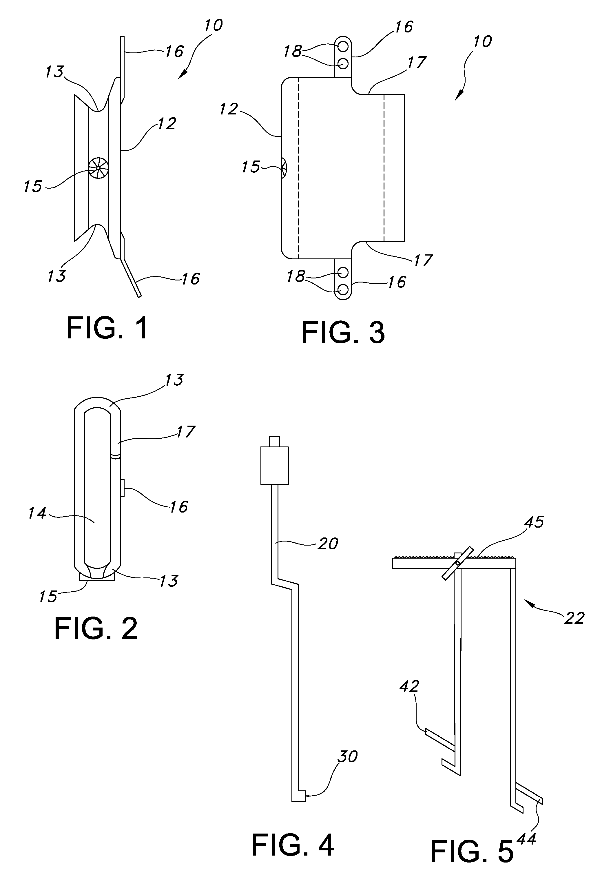
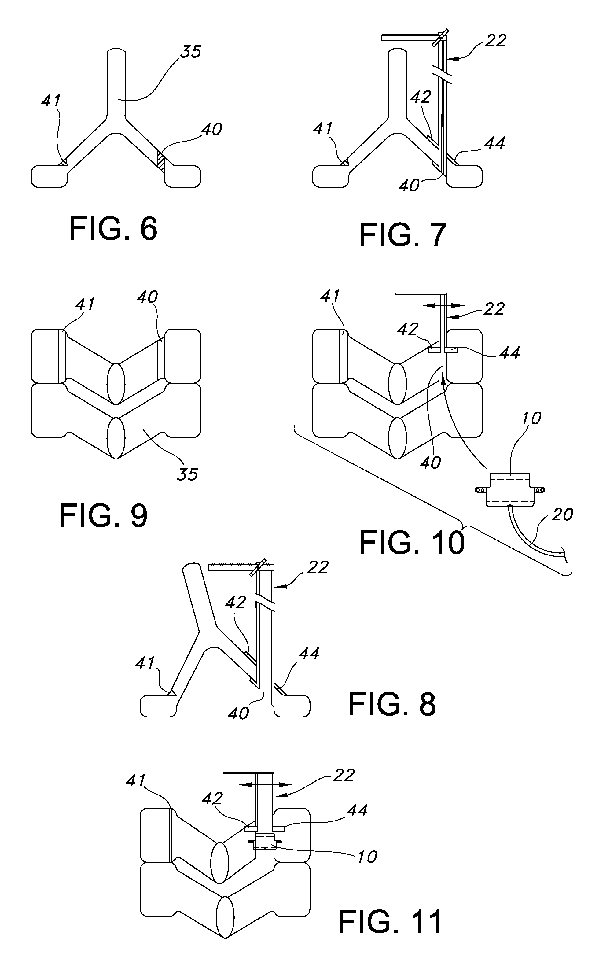
[0020]The Figures illustrate one embodiment of an implant 10 according to the present invention. The implant 10 can have a variety of shapes and sizes, but preferably has a size and a geometry that enables it to be positioned in a an open door fashioned space, and to remain securely positioned while healing and fusion take place. The design can also be altered to be utilized in a bisected spinous process. Moreover, the implant 10 preferably has a substantially low profile, to prevent potential abrasion or damage to surrounding tissue. A “low profile” implant does not substantially extend outside of the cervical area. In other words, the implant does not extend outside substantially past the cervical area.

[0021]The implant can be made of any biocompatible material known to those of skill in the art to be useful in spinal implants. Examples of such materials include, but are not limited to, polyketones such as polyetheretherketone (PEEK), poly ether ketone ketone ether ketone (PEKKEK)...


PUM


Abstract

A hollow non-load-bearing spinal implant having a hollow body and an attachment device for attaching the implant. A method of inserting a non-load-bearing spinal implant by inserting the laminoplasty implant into a prepared space in a spine, positioning the implant within the prepared space and affixing the implant to the spine.

Description

[0001]The present invention relates to laminoplasty and more particularly to laminoplasty implants.[0002]A condition associated with aging is spondylolsis, in which intervertebral disc lose water and become less dense. These degenerative changes near the disk can cause an overgrowth of the bone, producing bony spurs called, “osteophytes” that can compress the spinal cord. The constriction of the spinal cord in the cervical spine often produces pain, weakness, or loss of feeling in extremities. Other causes for narrowing of the spinal canal include disc shrinkage, which causes the disc space to narrow and the annulus to bulge and mushroom out, resulting in pressure on the spinal cord. Degenerative arthritis of facet joints can cause joints to enlarge, or the vertebra to slip with respect to each other, also compressing the spinal cord. Instability between vertebra, such as caused by stretched and thickened ligaments can also produce pressure on the spinal cord and nerve roots.[0003]C...

Claims


Application Information

Patent Timeline
IPC IPC(8): A61F2/44A61B17/56
CPCA61B17/7071
Inventor CANNESTRA, ANDREW F.
Owner BLUE FURY CONSULTING
Why Eureka
Try Eureka