Method for increasing performance of a stirling or free-piston engine

a technology of free-piston or stirling engine and performance improvement, which is applied in the direction of machines/engines, closed-cycle hot gas positive displacement engine plants, etc., can solve the problems of detriment to the performance and durability of the machine, and achieve the effect of improving performan

Inactive Publication Date: 2010-03-18
NEXTWAVE SOLAR
View PDF4 Cites 4 Cited by
  • Summary
  • Abstract
  • Description
  • Claims
  • Application Information

AI Technical Summary

Benefits of technology

[0022]The present invention advantageously fills the aforementioned deficiencies by providing a method of improving the performance of a free-piston or Stirling engine.
[0023]In order to maximize forces created in the hot space, the working fluid is contained in the hot space of the work space for a longer period of time than typical in Stirling cycle machines until it is allowed to flow, preferably via a passageway, to the cold space of the work space. Various passageways have been employed in the art and the present invention has applicability to all known methods of porting via a passageway, or set of passageways, working fluid from the hot space to the cold space or from the cold space to the hot space. In the preferred embodiment of the present invention, the passageway would be comprised of an uppermost displacer port, or entry port, and a bottom displacer port, or exhaust port. The entry port would have a one way check valve or other restrictive apparatus that serves to block flow of working fluid from the hot space. This reduces the relatively free flow of the working fluid and contains it in the hot space. In the preferred embodiment of the present invention, the exhaust port can be preferably positioned in the lower segment of the outward stroke of the displacer piston. This solves the problem of premature release of the working fluid from the hot working space as the relatively sealed exhaust port serves as a closed valve, halting release into the passageway. Therefore, for purposes of the heating or expansion portion of the cycle, the entry port is an open port only when the piston begins to pass by it on the outward portion of its stroke effectively remaining an open and free flowing port in the desired outward direction away from the hot space until it is again closed by the piston moving past it on the inward portion of its stroke. This is an improvement in that the combination of the closed entry port and the closed exhaust port during the heating portion of the cycle has the effect of keeping the working fluid in the hot space for a longer period allowing it to heat and thus expand more and with more force than if it were allowed to flow freely into the passageway.
[0024]Upon the return of the working fluid from the cold space to the hot space, the exhaust port is blocked by means of a one way valve contained in close proximity to the exhaust port. The one-way valve in the closed position serves to block entry into the displacer piston thus allowing the fluid to move from the cold space in this part of the cycle, to the hot space which has been recently relatively evacuated. The working fluid enters the hot space through the entry port passing through a one way valve, mounted in close proximity to the entry port, which now opens to allow the working fluid to flow through the valve and into the hot space via the entry port. In properly timed machines, the entry of the working fluid, the subsequent closing of the one way valve and the near end of the inward displacer piston stroke can have the effect of creating a gas spring at the innermost portion of the displacer piston stroke, which is an improvement in the forces that cause the reversal motion at the end of the piston stroke at the beginning of each cycle. Once this occurs, this cycle ends and a new cycle can begin.

Problems solved by technology

Side forces are generally seen by those skilled in the art as having a detrimental effect on performance and durability of the machine.

Method used


Image

  • Method for increasing performance of a stirling or free-piston engine
  • Method for increasing performance of a stirling or free-piston engine
  • Method for increasing performance of a stirling or free-piston engine

Examples


Embodiment Construction

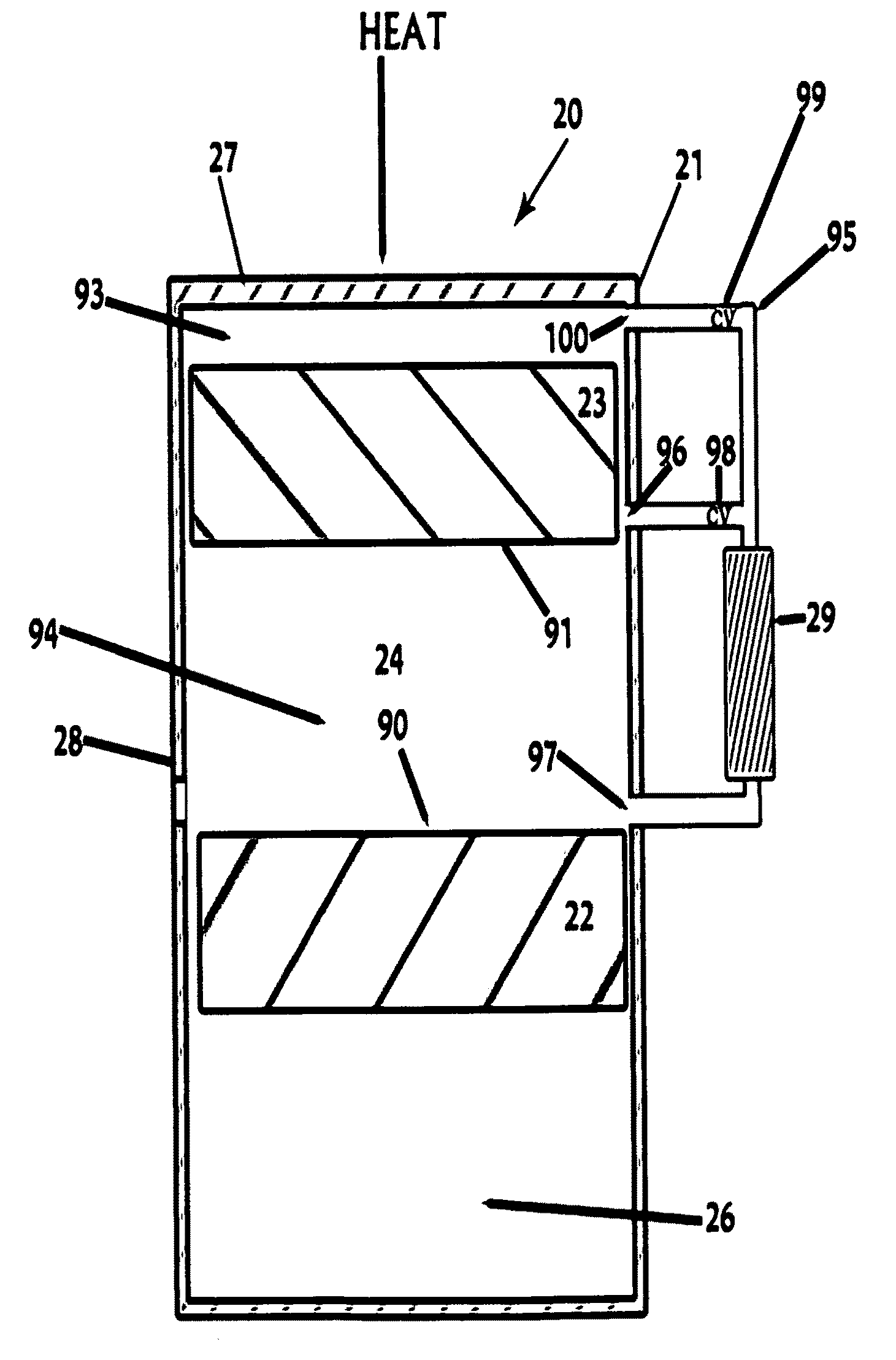
[0045]In describing the preferred embodiment of the invention which is illustrated in the drawings, specific terminology will be resorted to for the sake of clarity. However, it is not intended that the invention be limited to the specific terms so selected and it is to be understood that each specific term includes all technical equivalents which operate in a similar manner to accomplish a similar purpose. For example, the word connected or terms similar thereto are often used. They are not limited to direct connection but include connection through other elements where such connection is recognized as being equivalent by those skilled in the art. For example, a check valve or similar term thereto is often used. The term is not limited to a certain type of check valve but rather includes means to allow flow in one direction while preventing flow in another direction where such a means is recognized as being equivalent by those skilled in the art.

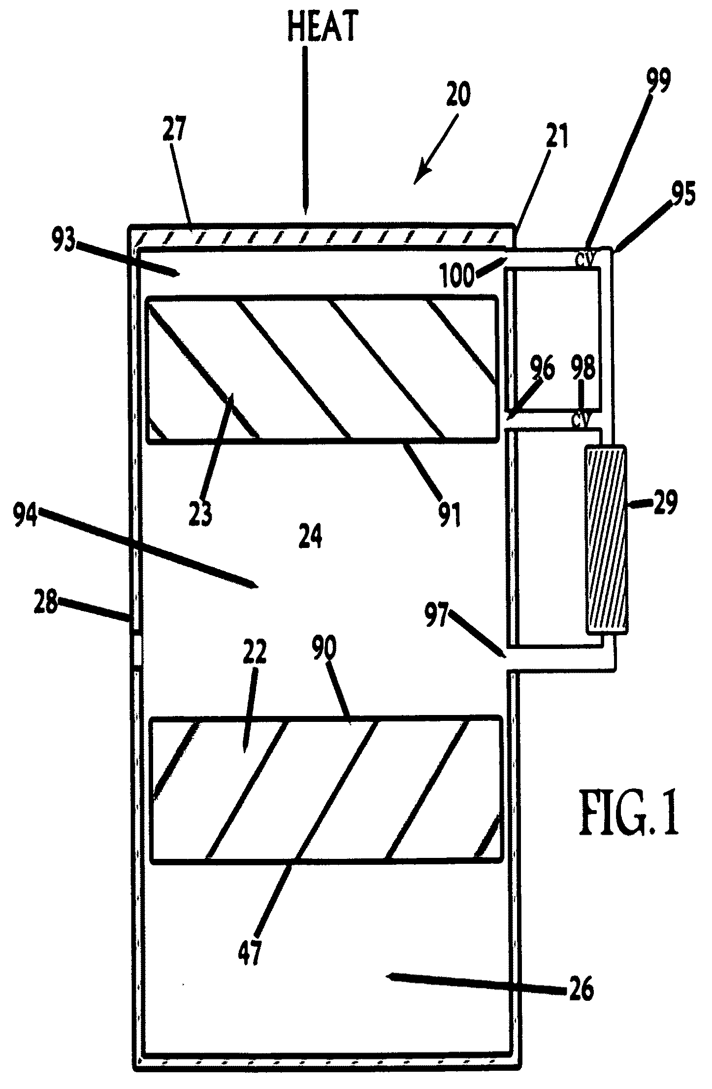
[0046]Referring to FIG. 1, free pist...


PUM


Abstract

A method for improving performance of a free-piston engine, also comprising various other engines such as Stirling Engines, Ericsson engines, Stirling cryocoolers and other external combustion or hot air engines. The improvement is the inclusion of a means, such as a valve or set of valves interposed in a passageway, to contain the working fluid (gas) in the hot or expansion work area so that increased work can occur; or the improvement is by means of piston blocking a port to the working gas passageway such that working gas is contained in the work space such that increased work can occur. The improvement reduces or ideally eliminates free flow of fluid until such time in the cycle where valve or port opens and allows the fluid to flow to the passageway from one space to the other.

Description

CROSS-REFERENCE TO RELATED APPLICATIONS[0001]Not ApplicableSTATEMENT REGARDING FEDERALLY SPONSORED RESEARCH OR DEVELOPMENT[0002]Not ApplicableREFERENCE TO SEQUENCE LISTING, TABLE, OR A COMPUTER PROGRAM LISTING COMPACT DISK APPENDIX[0003]Not ApplicableBACKGROUND OF THE INVENTION[0004]1. Field of the Invention[0005]This invention relates generally to improving the performance of a free-piston or Stirling engine. Stirling engines and similar motors are distinguished as motors operated by expansion and / or contraction of a unit of mass of motivating medium. The unit of mass is a gas which is heated or cooled in one of a plurality of constantly communicating expansible chambers and freely transferable therebetween. The present invention more specifically relates to having means to control rate of flow of mass between chambers.[0006]2. Technical Background[0007]Thermal differences may be used to power an engine to provide the thermal dynamic sources producing mechanical and electrical powe...

Claims


Application Information

Patent Timeline
Patent Type & Authority Applications(United States)
IPC IPC(8): F02G1/05
CPCF02G1/05F02G1/0435
Inventor YEGGE, MARK EDWARD
Owner NEXTWAVE SOLAR
Why Eureka
Try Eureka