Pneumatic tire

a technology of pneumatic tires and tyres, applied in the field of pneumatic tires, can solve problems such as bias wear, and achieve the effect of maintaining rollover resistance, improving wear resistance and braking performan

Active Publication Date: 2010-03-18
THE YOKOHAMA RUBBER CO LTD
View PDF3 Cites 25 Cited by
  • Summary
  • Abstract
  • Description
  • Claims
  • Application Information

AI Technical Summary

Benefits of technology

[0055]A pneumatic tire according to the present invention provides an effect of improving wear resistance and braking performance while maintaining the rollover resistance.

Problems solved by technology

This may cause portions of the tread to be worn to different degrees depending on the travel conditions, resulting in biased wear.

Method used


Image

  • Pneumatic tire
  • Pneumatic tire
  • Pneumatic tire

Examples


embodiments

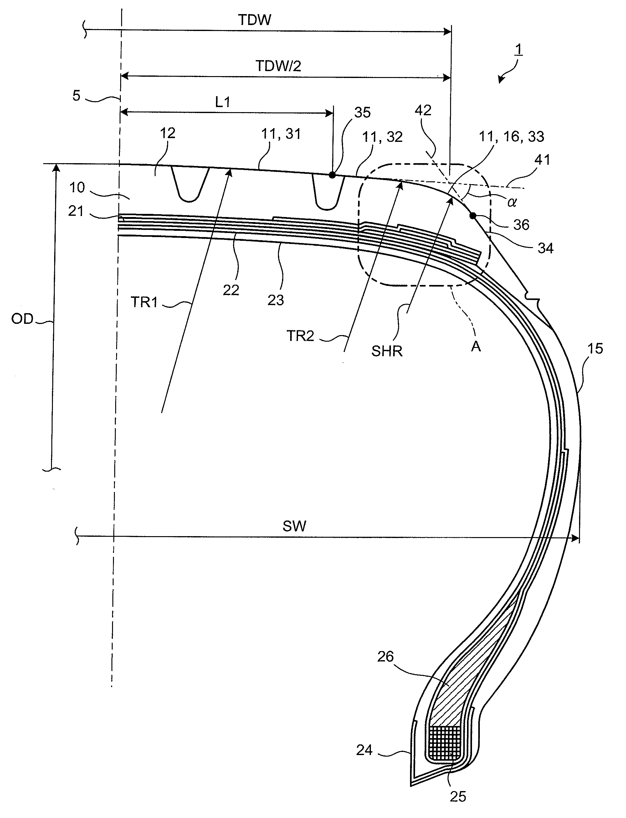
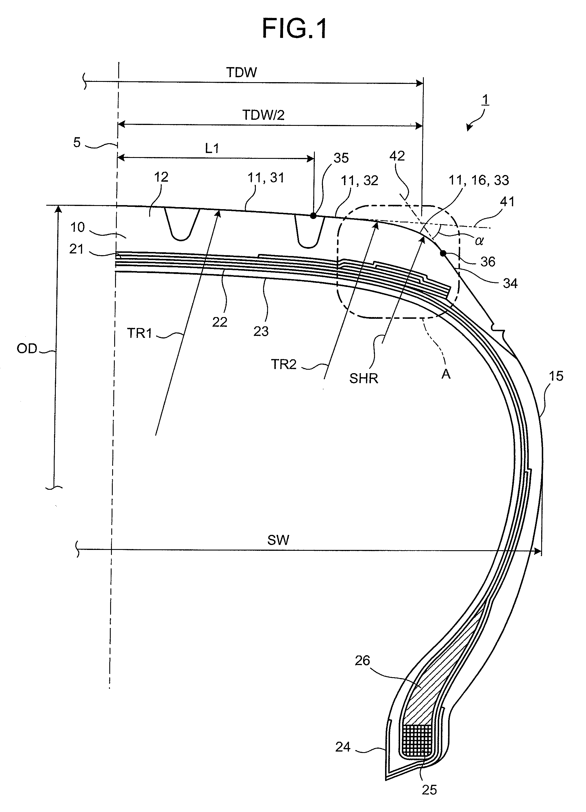
[0136]In the following description, a tire width direction is a direction parallel to a rotation axis of a pneumatic tire. An inner side in the tire width direction is a side being closer to a tire equatorial plane in the tire width direction, and an outer side in the tire width direction is an opposite side of the side being closer to the tire equatorial plane in the tire width direction. A tire diameter direction is a direction orthogonal to the rotation axis, and a tire circumferential direction is a direction in which the pneumatic tire rotates about the rotation axis serving as a center axis of its rotation. FIG. 1 is a meridional cross section of relevant portions of a pneumatic tire according to the present invention. A pneumatic tire 1 shown in FIG. 1 includes a tread 10 provided in a radially outermost portion of the tire, seen in a meridional cross section. On a lateral edge of the tread 10, i.e., from around a shoulder 16 up to a radially inner predetermined portion, is p...

examples

[0228]The following describes performance evaluation tests conducted using pneumatic tires 1 according to the present invention and pneumatic tires to be compared as comparative examples with the pneumatic tires 1 according to the present invention. Seven types of performance evaluation tests were conducted. For each test, a double-lane change test, and test run on a test course were performed.

[0229]As one of the seven performance evaluation tests, a first test method was conducted such that pneumatic tires 1 of size 205 / 45R17 were mounted on rims, then attached to a vehicle with an engine size of 1500 cc, and test run was performed. An evaluation method for each test item was conducted by performing a double-lane change test (elk test) specified by ISO3888-2 on the vehicle with the test pneumatic tires, and then by determining rollover resistance depending on whether the wheels of the vehicle were lifted up. Determination was made as indicated by circles for wheels not lifted up at...


PUM


Abstract

To provide a pneumatic tire achieving improved wear resistance and improved handling performance while maintaining rollover resistance, a tread surface 11 is formed of a center arc 31, a shoulder-side arc 32, and a shoulder arc 33. The tread surface 11 is formed such that a value given by F1=L1 / (TDW×0.5) falls in the range of 0.64≦F1≦0.7, a value given by F2=TR1 / OD falls in the range of 1.2≦F2≦2.0, a value given by F3=TR2 / TR1 falls in the range of 0.1≦F3≦0.2, and a value given by F4=(β×TDW) / (100×SW) falls in the range of 0.35≦F4≦0.48, where L1 is an outline range being a width from an equatorial plane 5 to an edge of the center arc 31, TDW is an extended tread width, TR1 is a curvature radius of the center arc 31, TR2 is a curvature radius of the shoulder-side arc 32, OD is a tire outside diameter, SW is a total width, and β is an aspect ratio.

Description

TECHNICAL FIELD[0001]The present invention relates to a pneumatic tire. The invention particularly relates to a pneumatic tire including a tread surface whose cross section is formed of a plurality of arcs.BACKGROUND ART[0002]In pneumatic tires, different areas of a tread are generally used when traveling in a straight line and in a curved line. This may cause portions of the tread to be worn to different degrees depending on the travel conditions, resulting in biased wear. Some conventional pneumatic tires have a tread of an appropriate shape so as to reduce biased wear. In a pneumatic radial tire described in Patent Document 1 for example, aiming to make uniform distribution of contact pressure and contact length in the tread being in contact with the ground, the tread is formed to have a crown shape including three arcs of different curvature radii such that the curvature radii of the arcs and the lateral widths of the arcs all fall in appropriate ranges. This allows the tread to...

Claims


Application Information

Patent Timeline
Patent Type & Authority Applications(United States)
IPC IPC(8): B60C11/00
CPCB60C3/04B60C3/06B60C9/28B60C11/0083B60C11/01B60C11/005B60C11/0309B60C2011/0369B60C13/003B60C11/0058B60C2011/0025B60C11/0306B60C9/2009B60C11/24B60C2015/009Y02T10/86
Inventor MATSUNAGA, FUTOSHIMORITA, KENICHITAKEI, HIROMITSU
Owner THE YOKOHAMA RUBBER CO LTD
Why Eureka
Try Eureka