Spiral rf-induction antenna based ion source for neutron generators

a technology of ion source and generator, which is applied in the direction of light sources, accelerators, electric discharge tubes, etc., can solve the problems of requiring relatively high operational pressure and finite life-time disadvantages

Inactive Publication Date: 2010-03-18
RGT UNIV OF CALIFORNIA
View PDF7 Cites 27 Cited by
  • Summary
  • Abstract
  • Description
  • Claims
  • Application Information

AI Technical Summary

Problems solved by technology

The former has the disadvantage of a finite life-time due to antenna surface deterioration.
The latter has the disadvantage of requiring relatively high operational pres...

Method used


Image

  • Spiral rf-induction antenna based ion source for neutron generators
  • Spiral rf-induction antenna based ion source for neutron generators
  • Spiral rf-induction antenna based ion source for neutron generators

Examples


Embodiment Construction

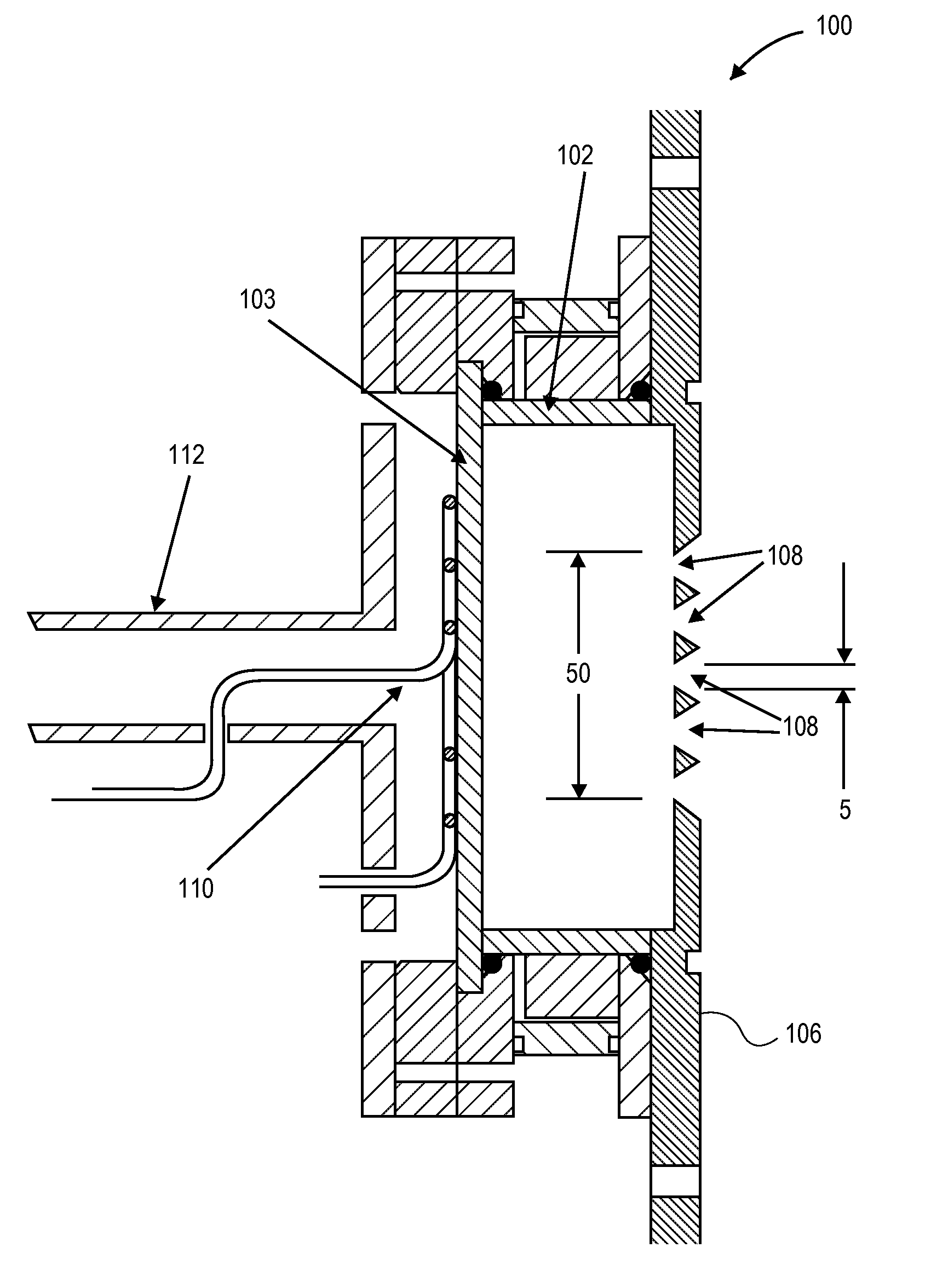
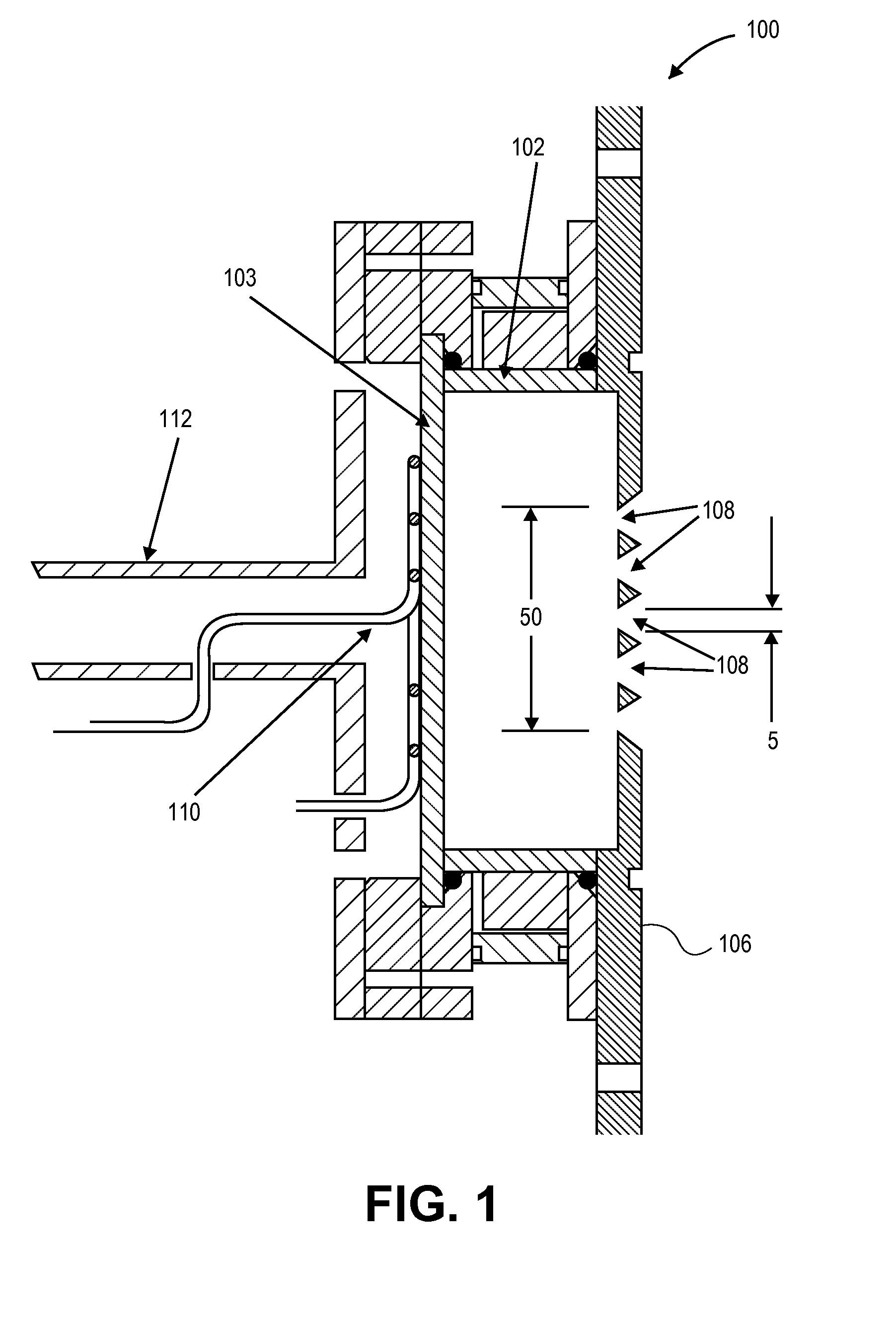
[0018]By way of this invention, a plasma is generated using a spiral shaped RF-antenna disposed proximate a flat RF-window. This arrangement has been shown to provide high plasma densities at low operating gas pressure. Both properties are needed for sealed or semi-sealed operation.

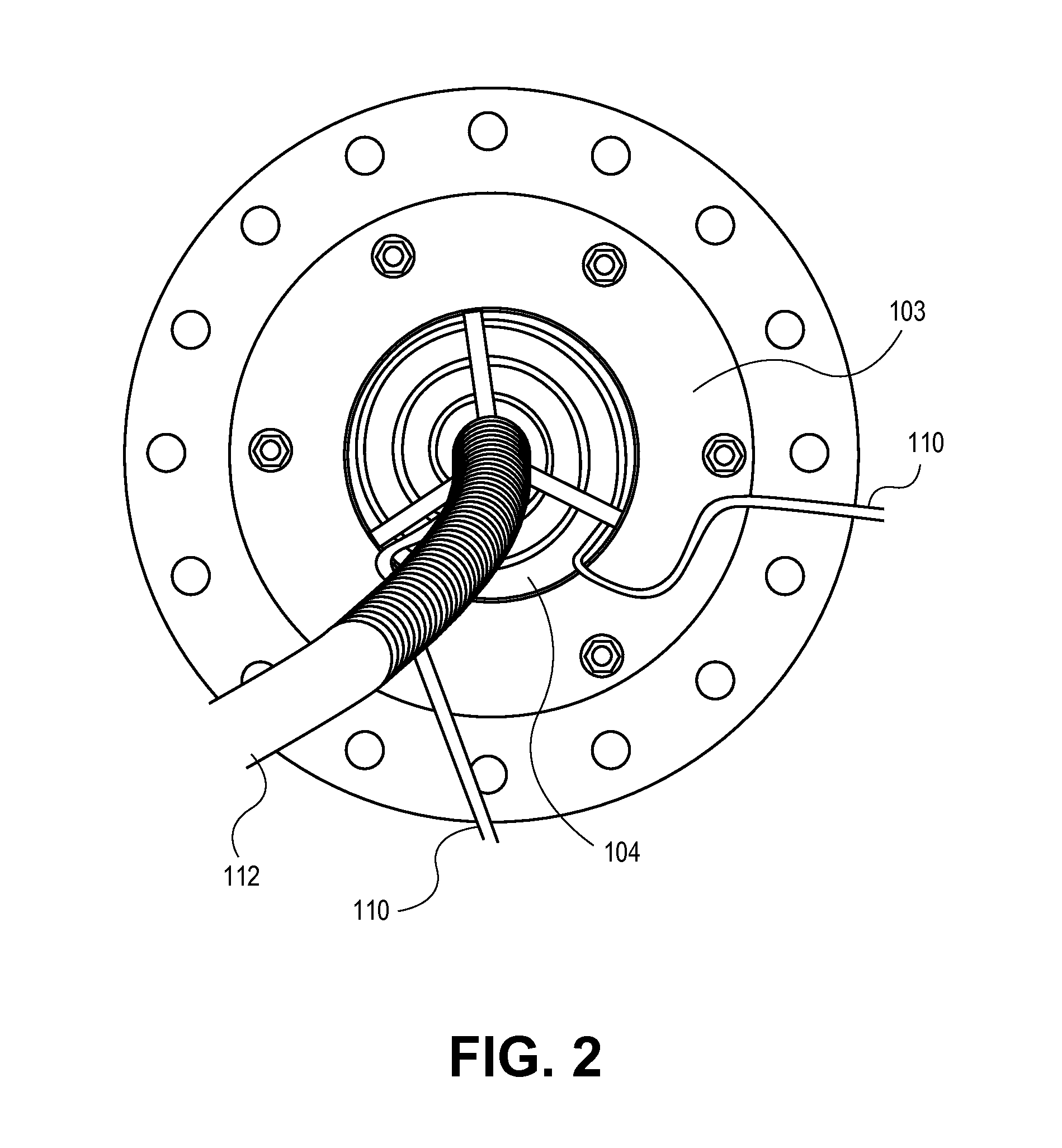
[0019]With reference to FIG. 1, an ion source 100 according to this invention is shown, in which a cylindrical alumina (Al2O3) plasma chamber 102 is illustrated. At the closed end 103 of chamber 102, a window 104 is provided. The window may be made alternatively from quartz, alumina or sapphire. At the other end of the chamber, facing the downstream target, an extraction plate 106 is provided, said plate 106 including an array of extraction apertures 108 through which ions generated in the plasma formed within the chamber may be extracted. In one embodiment the apertures are provided in the form of a series of parallel slits. Sitting atop the window 104 is a flat, spiral RF antenna 110. As illustrate in t...


PUM


Abstract

An ion source for the generation of hydrogen or deuterium ions is disclosed, said source suitable for the generation of D-D and D-T neutrons, wherein the body of the ion source is cylindrical, and disposed at one end of the ion source opposite the extraction plate, is a single, spiraled RF coil antenna, in which the spiraled coils are flat.

Description

CROSS-REFERENCE TO RELATED APPLICATIONS[0001]This application claims priority to Provisional U.S. Patent Application No. 61 / 046,307 filed Apr. 18, 2008, entitled Spiral RF-Induction Antenna Based Ion Source for Neutron Generators, which application is incorporated herein by reference.STATEMENT OF GOVERNMENTAL SUPPORT[0002]The invention described and claimed herein was made in part utilizing funds supplied by the U.S. Department of Energy under Contract No. DE-AC02-05CH11231. The government has certain rights in this invention.BACKGROUND OF THE INVENTION[0003]1. Field of the Invention[0004]This invention relates generally to neutron imaging generators, and, more specifically to an improved ion source for such generators incorporating a spiral shaped RF antenna.[0005]2. Description of the Related Art[0006]Neutron generators are used in a variety of applications ranging from material identification for homeland security operations to cancer treatments for medical applications. Potentia...

Claims


Application Information

Patent Timeline
IPC IPC(8): H01J27/02
CPCH05H3/06H01J27/16
Inventor REIJONEN, JANI PETTERIHAHTO, SAMI K.
Owner RGT UNIV OF CALIFORNIA
Why Eureka
Try Eureka