Liquid crystal display

a technology of liquid crystal display and liquid crystal, applied in the direction of illuminated signs, display means, instruments, etc., can solve the problem of not partially highlighting the brightness of images, and achieve the effect of improving display quality and reducing power consumption

Active Publication Date: 2010-03-18
LG DISPLAY CO LTD
View PDF5 Cites 30 Cited by
  • Summary
  • Abstract
  • Description
  • Claims
  • Application Information

AI Technical Summary

Benefits of technology

[0024]An object of the present invention is to provide a liquid crystal display which is capable of supplying an optimum dimming signal based on an average picture level of input video data to an LED backlight unit, so as to reduce power consumption and improve display quality.

Problems solved by technology

However, the liquid crystal display using the LED backlight unit is disadvantageous in that it cannot partially emphasize the brightness of an image displayed on the liquid crystal panel 2 using the LED backlight unit because it generates the dimming signal DS based on the input data RGB from one predetermined dimming curve.

Method used


Image

  • Liquid crystal display
  • Liquid crystal display
  • Liquid crystal display

Examples


Embodiment Construction

[0040]Reference will now be made in detail to the preferred embodiments of the present invention, examples of which are illustrated in the accompanying drawings. Wherever possible, the same reference numbers will be used throughout the drawings to refer to the same or like parts.

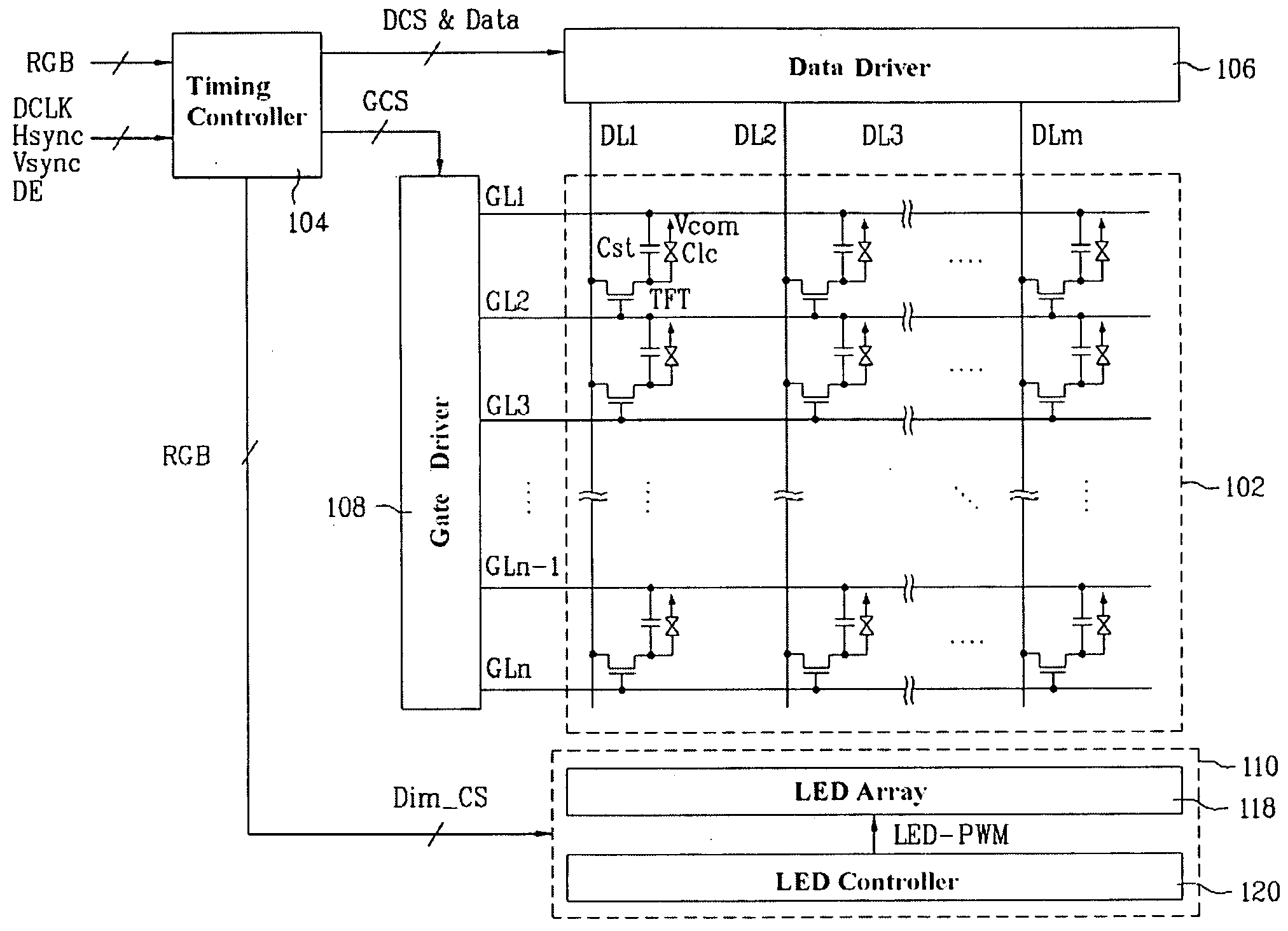
[0041]FIG. 3 is a schematic view of a liquid crystal display according to an embodiment of the present invention.

[0042]Referring to FIG. 3, the liquid crystal display according to the present embodiment comprises a liquid crystal panel 102 having a plurality of liquid crystal cells formed respectively in a plurality of pixel areas defined by intersections of a plurality of gate lines GL1 to GLn and a plurality of data lines DL1 to DLm, a data driver 106 for supplying data voltages to the data lines DL, a gate driver 108 for supplying scan signals to the gate lines GL, a timing controller 104 for controlling the data driver 106 and gate driver 108 and outputting a plurality of dimming signals Dim_CS based on ...


PUM


Abstract

Disclosed herein is a liquid crystal display capable of reducing a side effect during local LED dimming to reduce power consumption and improve display quality. The liquid crystal display includes a liquid crystal panel having a plurality of liquid crystal cells formed respectively in a plurality of pixel areas defined by intersections of a plurality of gate lines and a plurality of data lines, a data driver for supplying data voltages to the data lines, a gate driver for supplying scan signals to the gate lines, a timing controller for controlling the data driver and gate driver and outputting a plurality of dimming signals based on an average picture level (APL) detected based on video data supplied to the liquid crystal panel, and a light emitting diode (LED) backlight unit for partitioning the liquid crystal panel into a plurality of areas and supplying appropriate pulse width modulation (PWM) control signals based on the dimming signals to a plurality of LED arrays installed to correspond respectively to the partitioned areas, to supply light to the liquid crystal panel.

Description

[0001]This application claims the benefit of the Korean Patent Application No. P2008-035158, filed on Apr. 16, 2008, which is hereby incorporated by reference as if fully set forth herein.BACKGROUND OF THE INVENTION[0002]1. Field of the Invention[0003]The present invention relates to a liquid crystal display, and more particularly, to a liquid crystal display which is capable of reducing power consumption and improving display quality.[0004]2. Discussion of the Related Art[0005]Recently, various flat panel display devices have been developed to reduce weight and volume which are disadvantages of a cathode ray tube. These flat panel display devices may be, for example, a liquid crystal display, a field emission display, a plasma display panel, a light emitting device, and the like.[0006]The liquid crystal display, among the flat panel display devices, includes a liquid crystal panel including a plurality of liquid crystal cells arranged in matrix form and a plurality of control switc...

Claims


Application Information

Patent Timeline
Patent Type & Authority Applications(United States)
IPC IPC(8): G09G3/36
CPCG09G3/342G09G2320/064G09G2360/16G09G2330/021G09G2320/0646G02F1/133G09G3/20G09G3/32G09G3/36
Inventor PARK, JOON KYUKIM, JONG HOON
Owner LG DISPLAY CO LTD
Why Eureka
Try Eureka