Video decoding method and video encoding method

a video decoding and video encoding technology, applied in the field of prediction-based video decoding methods and prediction-based video encoding methods, can solve the problems of large amount of bits that have to be spent to really conserve the sharpness of original images, limited available bitrate in many applications, and may also be amplified coding artifacts, so as to reduce coding artifacts

Inactive Publication Date: 2010-03-18
PANASONIC CORP
View PDF13 Cites 30 Cited by
  • Summary
  • Abstract
  • Description
  • Claims
  • Application Information

AI Technical Summary

Benefits of technology

[0073]The present invention can generate an image with reduced coding artifacts that are caused...

Problems solved by technology

Obviously, compressing pictures to a low bitrate and hiding coding artifacts are conflicting goals.
Therefore, a large amount of bits have to be spent to really conserve the sharpness of the original images.
Because the available bitrate is strictly limited in many applications, post processing techniques like unsharp masking or local contrast enhancement is applied to bring ...

Method used


Image

  • Video decoding method and video encoding method
  • Video decoding method and video encoding method
  • Video decoding method and video encoding method

Examples


first embodiment

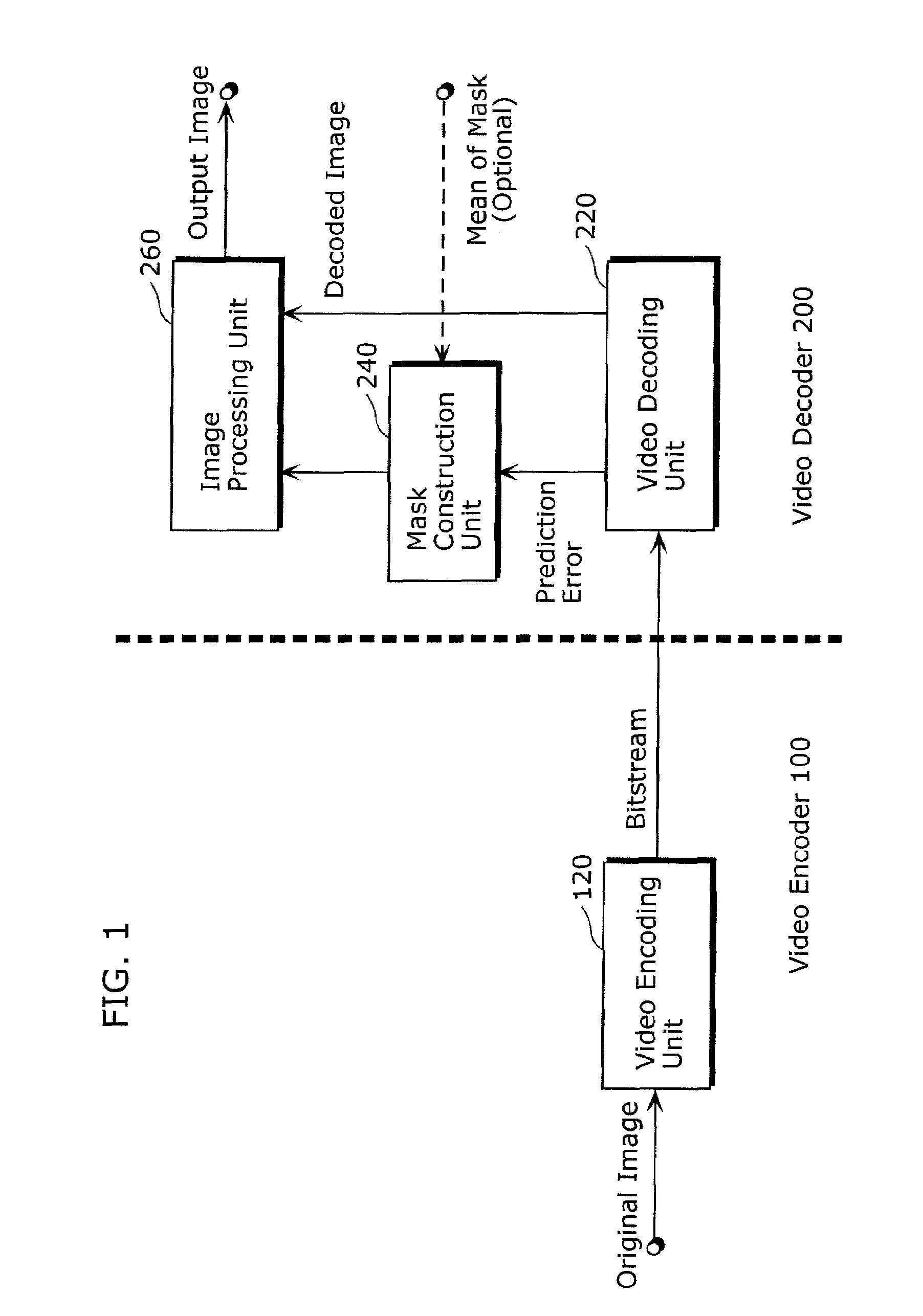
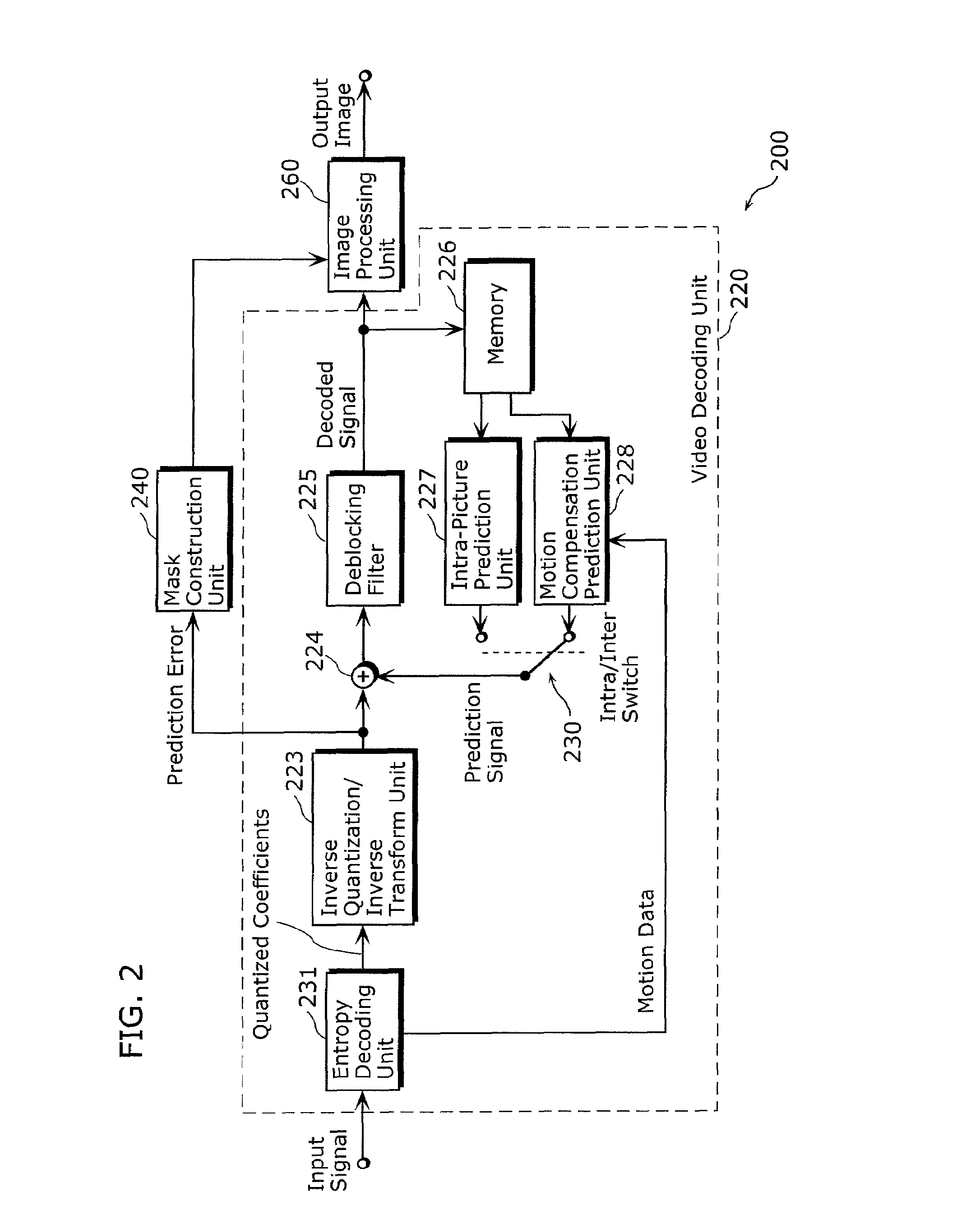
[0123]FIG. 1 is a block diagram illustrating an example of configuration of a codec system employing a mask-controlled image enhancement technique in accordance with the first embodiment of the present invention. The codec system illustrated in FIG. 1 includes a video encoder 100 and a video decoder 200.

[0124]The video encoder 100 encodes a video sequence. The video encoder 100 includes a video encoding unit 120.

[0125]The video encoder 120 receives a video sequence including original images, applies a video encoding method on the received video sequence, and thereby generates a bitstream representing the encoded video sequence. The video encoding unit 120 transmits the generated bitstream to the video decoder 200. The video encoding method may be any conventional prediction-based encoding method, including MPEG-2 and H.264 / AVC.

[0126]For example, the video encoding unit 120 includes the same elements as those in the video encoder 500 illustrated in FIG. 11. The video encoding unit 12...

second embodiment

[0182]The video encoding method and the video decoding method in the second embodiment further enhance image quality of decoded images using statistical properties of original images. A mask is constructed based on a value of prediction error also in encoding processing. Statistical properties of an original image are analyzed and the resulting statistical properties are applied to the mask to compute statistical parameters. In decoding processing, the statistical properties obtained by the analysis are used to apply post processing to a decoded image. Thereby, image quality of the decoded image can be enhanced more.

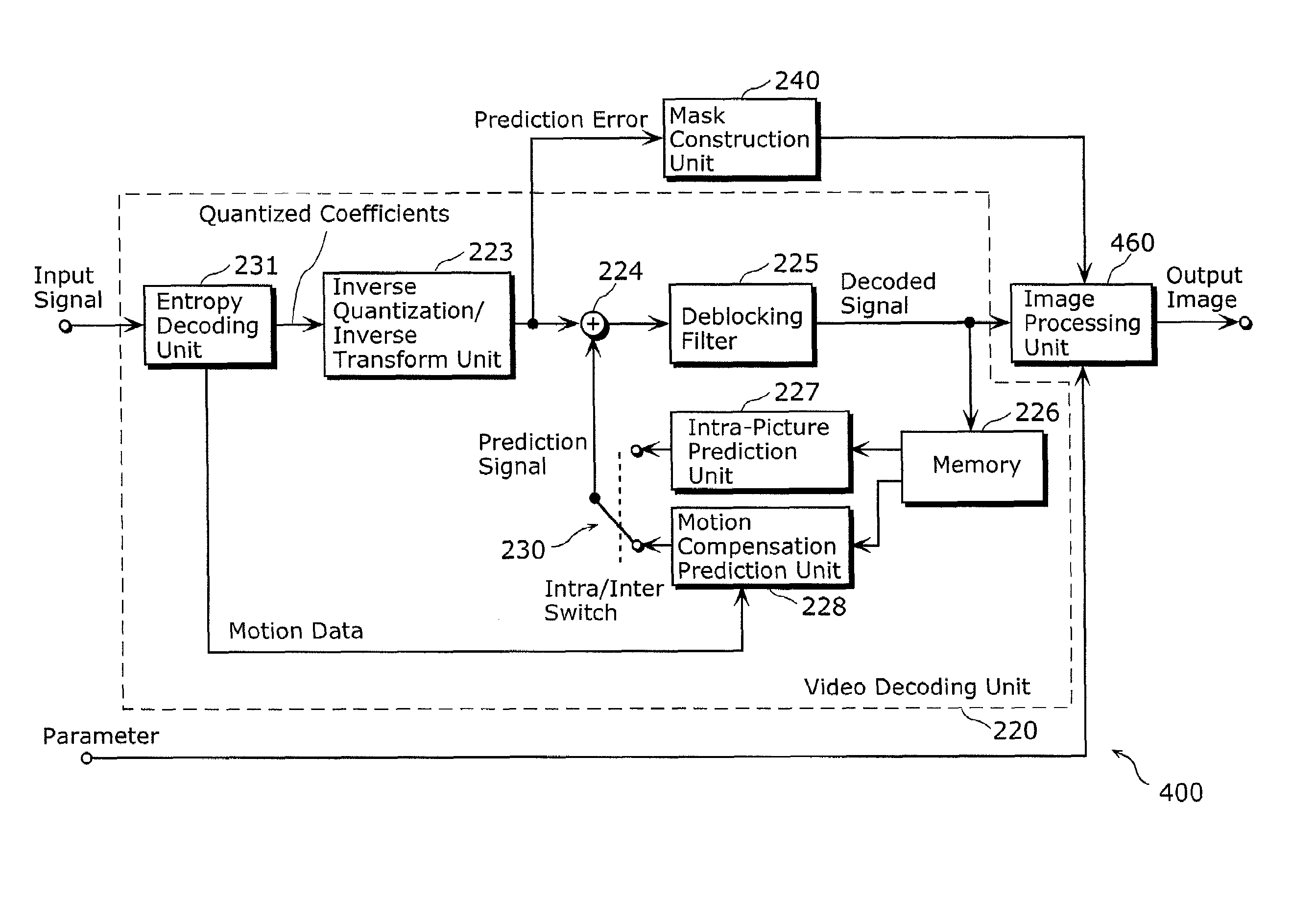
[0183]FIG. 7 is a block diagram illustrating an example of configuration of a codec system employing a mask-controlled image enhancement technique in accordance with the second embodiment of the present invention. The codec system of FIG. 7 includes a video encoder 300 and a video decoder 400. Hereinafter, like elements in the image codec systems in the first and second ...


PUM


Abstract

The present invention prevents coding artifacts caused in applying image enhancement technologies to pictures that have been encoded and then decoded. A video decoder (200) decodes an encoded stream generated by encoding a prediction error that is a difference between an original image and a prediction image. The video decoder (200) includes: an entropy decoding unit (231) decoding the prediction error in the encoded stream; an adder (244) adding the decoded prediction error to a previously-generated decoded image to generate a decoded image; an image enhancement unit (260) performing a process of enhancing image quality of the generated decoded image to generate an enhanced image; and a mask construction unit (240) determining a weight coefficient for each image area based on the decoded prediction error. The image enhancement unit (260) generates an output image by computing a weighted sum of the decoded image and the enhanced image in accordance with the determined weight coefficient.

Description

TECHNICAL FIELD[0001]The present invention relates to prediction-based video decoding method and video encoding method, and corresponding apparatuses, and in particular to a method for post-processing decoded images to enhance subjective image quality, and a corresponding apparatus.BACKGROUND ART[0002]State-of-the-art video encoding techniques such as H.264 / AVC standard compress image or video data by accepting the loss of information caused by quantization. These techniques are optimized to keep the encoded pictures as close as possible to the original ones and to hide coding artifacts for the human viewer.[0003]Obviously, compressing pictures to a low bitrate and hiding coding artifacts are conflicting goals. One important aspect is, that even if no artifacts are visible, a loss of sharpness remains in many cases. Therefore, a large amount of bits have to be spent to really conserve the sharpness of the original images. Because the available bitrate is strictly limited in many app...

Claims


Application Information

Patent Timeline
IPC IPC(8): H04N7/26H04N7/32
CPCG06T5/002G06T5/003G06T2207/10016G06T2207/20036H04N19/85H04N19/61H04N19/117H04N19/137H04N19/44H04N19/172
Inventor KNICKER, FLORIANWEDI, THOMASRAMOND, ADRIEN
Owner PANASONIC CORP
Why Eureka
Try Eureka