Vehicle drive device

a technology of drive device and drive device, which is applied in the direction of motor/generator/converter stopper, propulsion parts, etc., can solve the problems that the space saving of the drive device for a hybrid vehicle is not sufficiently taken into account, and achieves the cooling of the electric circuit group, the reduction of surge voltage, and the length of the conductor member for electrically connecting the power element.

Inactive Publication Date: 2010-03-25
TOYOTA JIDOSHA KK
View PDF5 Cites 42 Cited by
  • Summary
  • Abstract
  • Description
  • Claims
  • Application Information

AI Technical Summary

Problems solved by technology

Furthermore, the saving of space for mounting the drive device for a hybrid vehicle is not sufficiently taken into consideration.

Method used


Image

  • Vehicle drive device
  • Vehicle drive device
  • Vehicle drive device

Examples


case 102

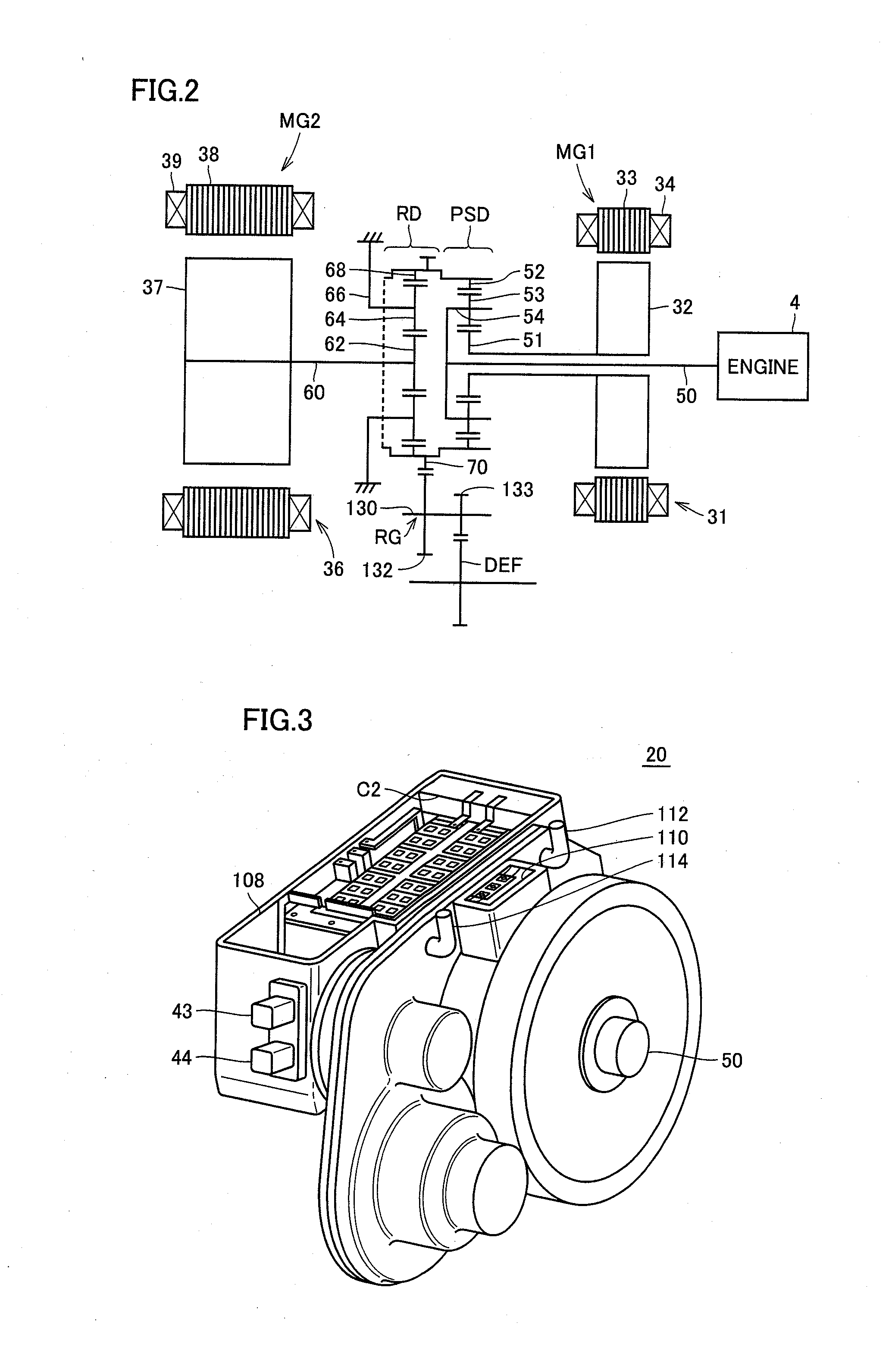
[0099]Case 102 is provided with an opening 108 for installing power control unit 21. In opening 108, capacitor C2 is housed on the inner left side (in the direction of vehicle travel), a power element substrate 120 and terminal bases 116, 118 are housed in the center portion, and reactor L1 is housed on the right side. When mounted on the vehicle, opening 108 is closed by a cover. It is to be noted that the arrangement may be reversed such that capacitor C2 is housed on the right side and reactor L1 is housed on the left side.

[0100]In other words, reactor L1 is positioned on one side of the rotation shaft of each of motor generators MG1 and MG2, and capacitor C2 is positioned on another side thereof. Power element substrate 120 is disposed in the region between capacitor C2 and reactor L1. Motor generator MG2 is disposed below power element substrate 120.

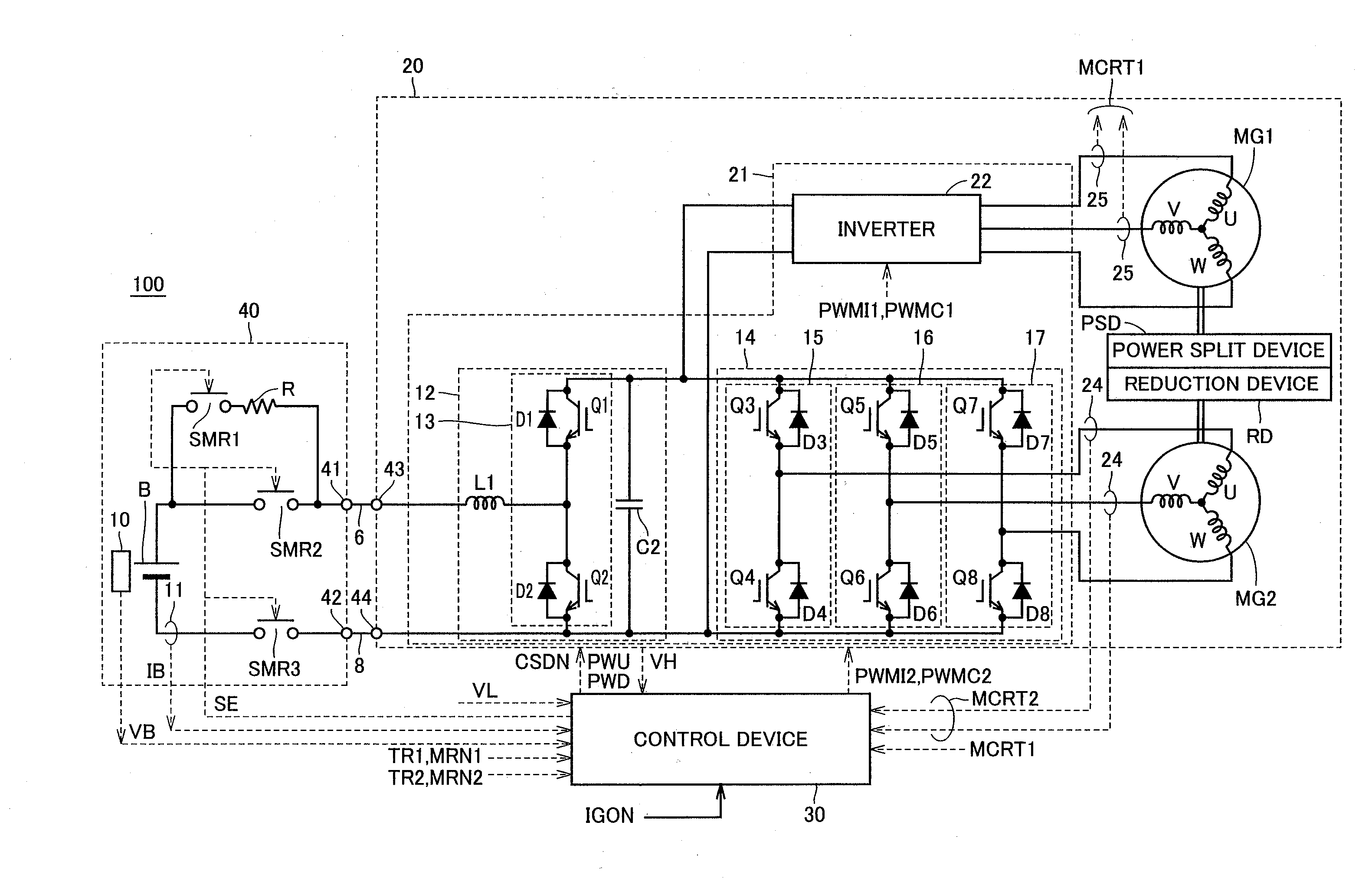
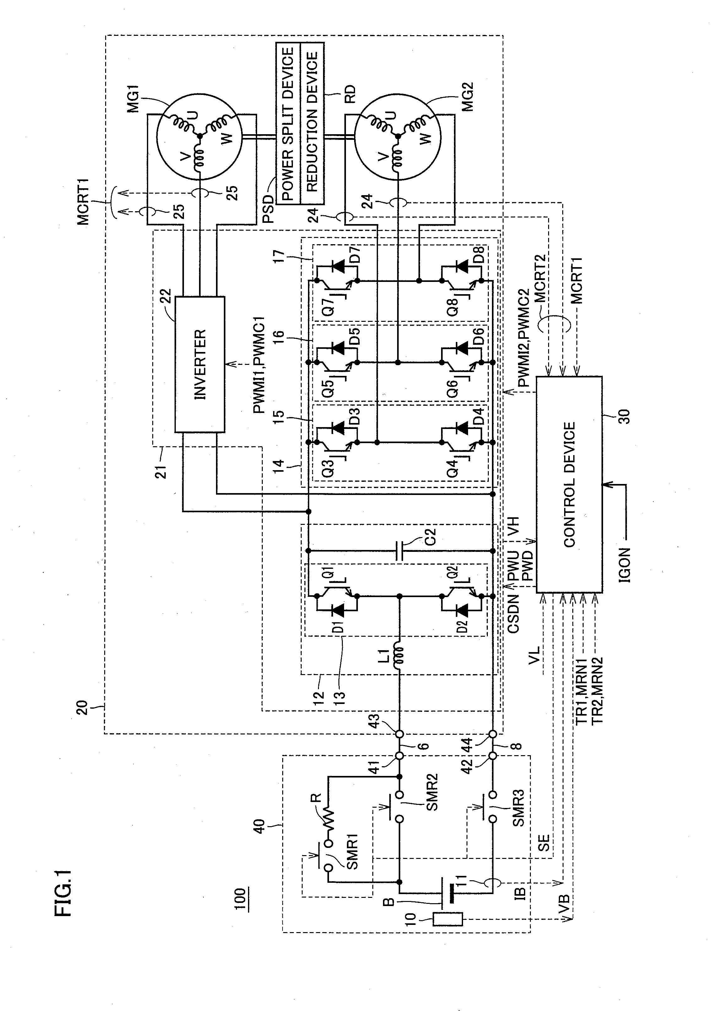
[0101]Power element substrate 120 is equipped with inverter 22 controlling motor generator MG1, inverter 14 controlling motor gene...


PUM

PropertyMeasurementUnit
voltageaaaaaaaaaa
voltageaaaaaaaaaa
poweraaaaaaaaaa

Abstract

A vehicle drive device includes a motor generator (MG2), a power control unit controlling the motor generator (MG2), and a case housing the motor generator (MG2) and the power control unit. The power control unit includes a first inverter driving the motor generator (MG2) and a voltage converter boosting a power supply voltage to apply the voltage to the first inverter. A reactor L1 which is a component of the voltage converter is disposed such that at least a portion of a core comes into contact with the case for heat exchange. Consequently, the heat is dissipated to the case having a large heat capacity for integral housing, to thereby allow the heat dissipation performance of the reactor (L1) arranged in the limited space to be ensured.

Description

TECHNICAL FIELD[0001]The present invention relates to a vehicle drive device, and more particularly to a vehicle drive device in which a motor and a power control unit drive-controlling the motor are housed in one case.BACKGROUND ART[0002]Japanese Patent Laying-Open Nos. 2004-343845 and 2001-119961 disclose techniques for reducing the drive device in size by housing a motor and an inverter in one case for integration in the drive device for a hybrid vehicle, as a kind of a vehicle drive device, provided with a motor as a vehicle driving power source.[0003]However, the drive device for a hybrid vehicle disclosed in each of Japanese Patent Laying-Open Nos. 2004-343845 and 2001-119961 has a structure merely having an inverter mounted on a motor, which leaves room for improvement in the position of the center of gravity of the vehicle with respect to the height direction when the device is mounted on the vehicle. Furthermore, the saving of space for mounting the drive device for a hybri...

Claims


Application Information

Patent Timeline
Patent Type & Authority Applications(United States)
IPC IPC(8): H02K11/00H01F27/22H05K7/20
CPCB60K1/02Y02T10/642B60K6/365B60K6/40B60K6/405B60K6/445B60K6/547B60K2001/003B60L2240/421B60L2240/423B60W10/08B60W20/00B60W2510/081B60W2710/083H02K9/22H02K11/0094H02K11/048H02K51/00H02M2001/007Y02T10/6239Y02T10/641B60K6/26Y10S903/909Y10S903/906Y02T10/62Y02T10/64H02M1/007H02K9/227H02K9/223H02K11/05H02K9/02
Inventor ENDO, YASUHIROMIZUTANI, RYOJITATEMATSU, KAZUTAKAYOSHIDA, TADAFUMI
Owner TOYOTA JIDOSHA KK
Why Eureka
Try Eureka