Rotary electric machine control system

a control system and electric machine technology, applied in the direction of electric generator control, dynamo-electric converter control, dynamo-electric gear control, etc., can solve the problems of not necessarily being the most efficient, and achieve the effect of improving the efficiency of the whole system

Inactive Publication Date: 2010-03-25
DENSO CORP
View PDF5 Cites 21 Cited by
  • Summary
  • Abstract
  • Description
  • Claims
  • Application Information

AI Technical Summary

Benefits of technology

[0020]It is therefore an object of the present invention to provide a control system, which enhances efficiency of an entire system including a rotary electric machine and an inverter.

Problems solved by technology

This means that, although the command current determined in accordance with the maximum efficiency characteristic line can drive the rotary electric machine at the maximum efficiency, it is not necessarily most efficient when an entire rotary electric machine system including the inverter is considered.

Method used


Image

  • Rotary electric machine control system
  • Rotary electric machine control system
  • Rotary electric machine control system

Examples


Embodiment Construction

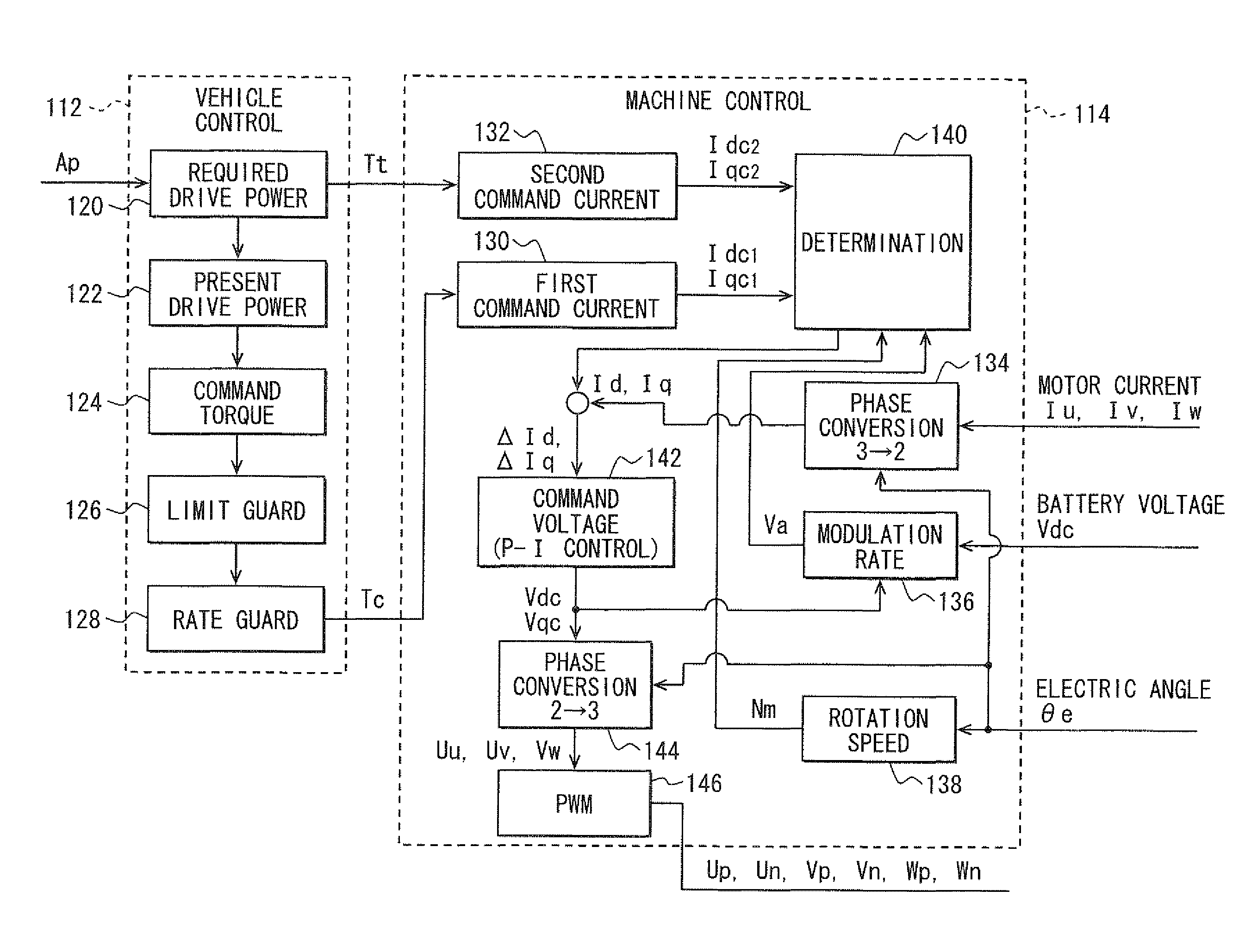
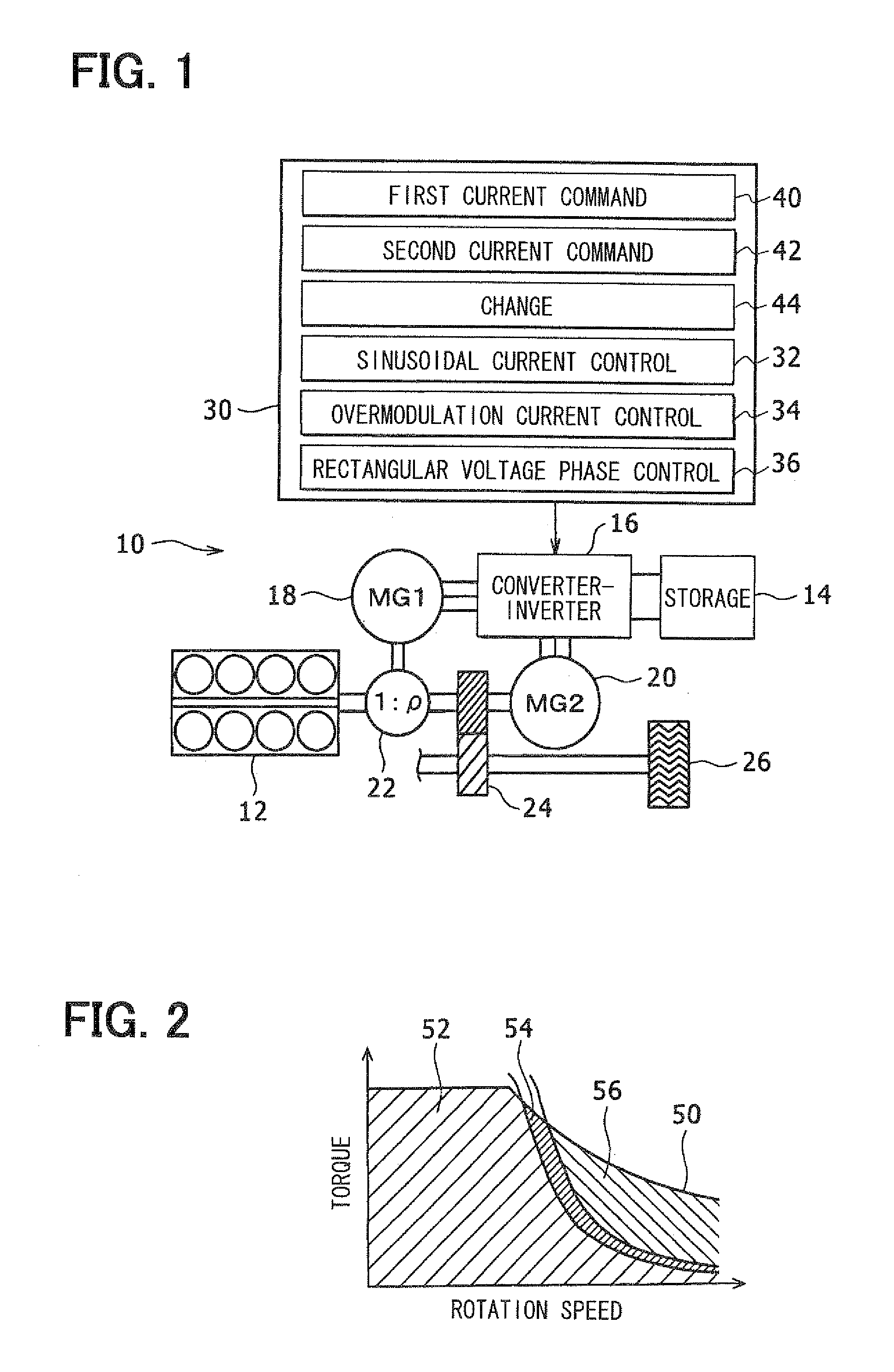
[0037]The present invention will be described in detail with reference to one exemplary embodiment of a rotary electric machine control system, in which a rotary electric machine is mounted in a vehicle. This control system may be applied to any other rotary electric machines, which are controlled by switching over control modes among a sinusoidal wave current control mode, an overmodulation current control mode and a rectangular wave voltage phase control mode. Although this control system controls two motor-generators, each of which has a motor function and a generator function, it may control one rotary electric machine having only a motor function and one rotary electric machine having only a generator function. Further, it may control only one motor-generator or three or more motor-generators.

[0038]Referring first to FIG. 1, a rotary electric machine control system 10 is provided for a rotary electric machine provided in a hybrid vehicle.

[0039]The vehicle has an engine 12 and a...


PUM


Abstract

A control unit for a rotary electric machine control system includes a first current command module, a second current command module and a change module. The first current command module controls the rotary electric machine based on a maximum efficiency characteristic line. The second current command module controls the rotary electric machine based on an early switching characteristic line, which is set at a retard angle side relative to the maximum efficiency characteristic line with a predetermined phase difference. When a control mode is switched over to a rectangular wave voltage phase control mode from an overmodulation current control mode in accordance with an increase in torque, the change module changes the current command from the first current command module to the second command current module.

Description

CROSS REFERENCE TO RELATED APPLICATION[0001]This patent application is based on and incorporates herein by reference Japanese Patent application No. 2008-243633 filed on Sep. 24, 2008.[0002]This patent application is related to co-pending U.S. patent applications arising from Japanese patent applications No. 2008-243648 filed on Sep. 24, 2008 (IPICS 122525-US-KK / nk) and No. 2008-243738 filed on Sep. 24, 2008 (IPICS 122524-US-KK-mik).FIELD OF THE INVENTION[0003]The present invention relates to a rotary electric machine control system and, more particularly, to a rotary electric machine control system, which switches over a control mode among a sinusoidal wave current control mode, an overmodulation current control mode and a rectangular wave voltage phase control mode.BACKGROUND OF THE INVENTION[0004]In driving a rotary electric machine by an inverter, a control mode is switched over among a sinusoidal wave current control mode, an overmodulation current control mode and a rectangula...

Claims


Application Information

Patent Timeline
Patent Type & Authority Applications(United States)
IPC IPC(8): H02P21/00H02P27/04H02P21/22H02P25/022H02P27/08
CPCB60K1/02Y02T10/7077B60K6/445B60L11/123B60L11/14B60L11/18B60L15/025B60L2240/421B60L2240/423B60W10/08B60W20/00B60W2510/081B60W2540/10B60W2710/083H02P21/0003Y02T10/6217Y02T10/6239Y02T10/643Y02T10/7005B60K6/365B60L50/16B60L50/50B60L50/61Y02T10/62Y02T10/64Y02T10/70Y02T10/7072B60W20/10B60W2510/24B60W2710/08
Inventor ITOH, TAKESHIOGAWA, TAKASHI
Owner DENSO CORP
Why Eureka
Try Eureka