Dual thin film precision resistance trimming

a thin film, precision technology, applied in the direction of positive temperature coefficient thermistors, iron-filament ballast resistors, instruments, etc., can solve the problems of changing the resistance of resistors, and achieve the effect of improving circuit performance, accurate sensing, and high resistan

Active Publication Date: 2010-03-25
STMICROELECTRONICS SRL +1
View PDF18 Cites 67 Cited by
  • Summary
  • Abstract
  • Description
  • Claims
  • Application Information

AI Technical Summary

Benefits of technology

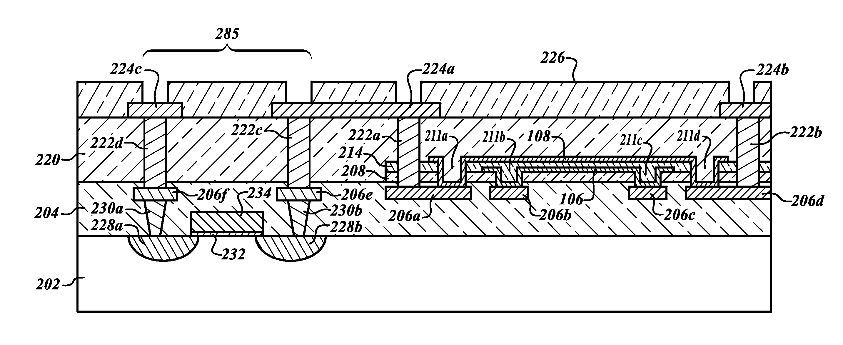
[0007]In another embodiment, the resistor is trimmed and used in a current sense configuration. In a current sense configuration, a resistor may be placed across the input terminals of an op amp. The op amp is used to sense and amplify the voltage drop across the resistor. Knowing the exact resistance of the resistor and the gain of the op amp will allow one to determine the amount of current flowing through the resistor for evaluating the parameter of interest. The value of the resistor can be more precisely set than just using standard process manufacturing techniques. The value of the resistance of the resistor will affect the range of currents detectable by the current sense configuration. For some sense circuits, a very low resistor may be preferred, while in other types of sense circuitry a higher resistance will provide more accurate sensing and better circuit performance. Thus, the ability to adjust the resistor may improve the effectiveness of a current sense circuit.
[0014]Alternatively, the purchaser of the chip may also trim the resistor just prior to using it in an end circuit. The user, upon purchase of the chip in its complete package form, may perform various tests on the integrated circuit package according to their desired end use of the completed circuit. The user can determine what resistance value is preferred and, by applying appropriate voltage to the terminals of the package, heat the resistor to the selected value and thus change the resistor to have a value which provides the preferred circuit performance.

Problems solved by technology

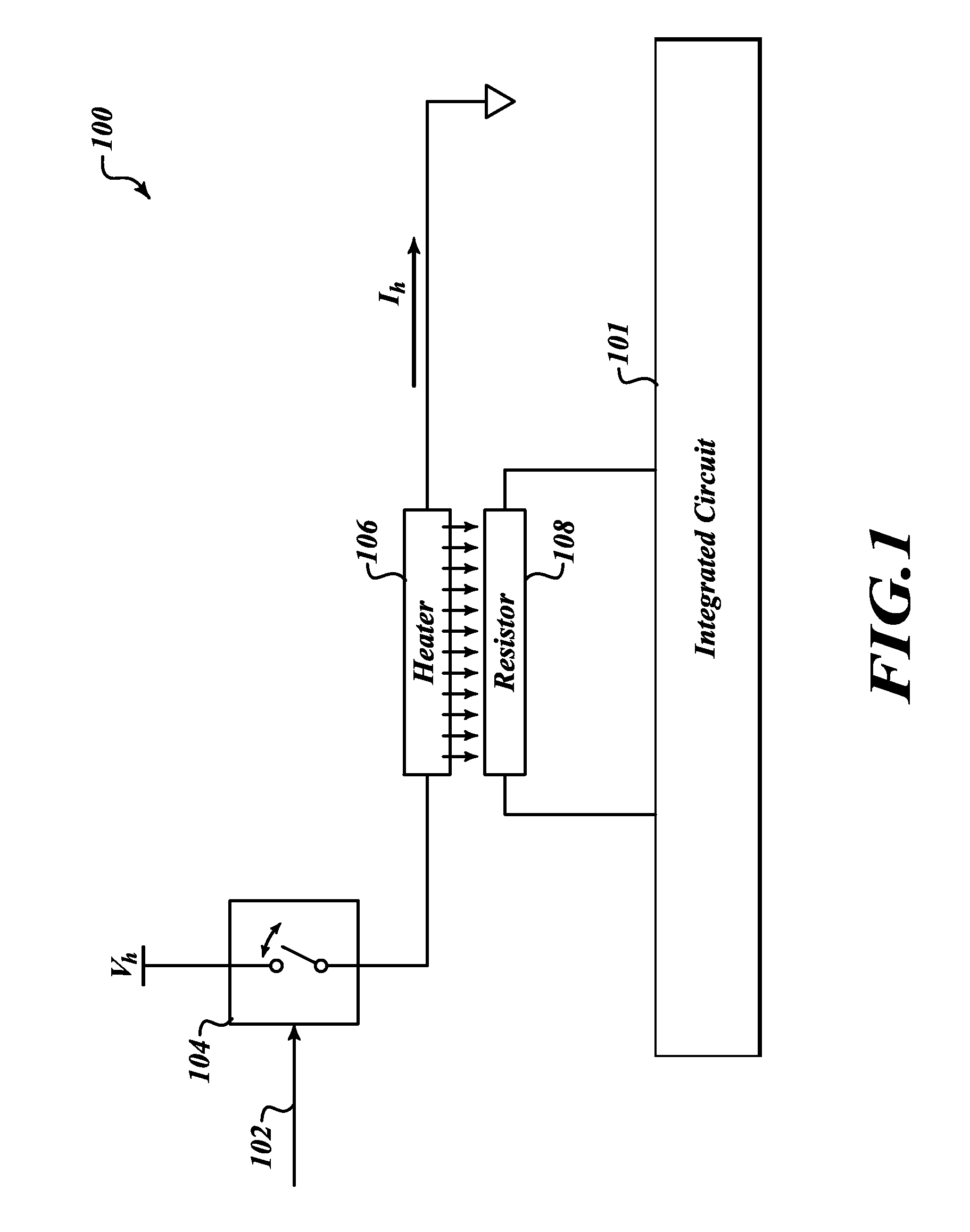
Separating the heater from the resistor by one or more thermal separators and applying a voltage to the heater results in changing the resistance of the resistor.

Method used


Image

  • Dual thin film precision resistance trimming
  • Dual thin film precision resistance trimming
  • Dual thin film precision resistance trimming

Examples


Embodiment Construction

[0027]In the following description, certain specific details are set forth in order to provide a thorough understanding of various disclosed embodiments. However, one skilled in the relevant art will recognize that embodiments may be practiced without one or more of these specific details, or with other methods, components, materials, etc. In other instances, well-known structures and methods associated with integrated circuits and semiconductor manufacturing / packaging processes have not been shown or described in detail to avoid unnecessarily obscuring descriptions of the embodiments.

[0028]Unless the context requires otherwise, throughout the specification and claims which follow, the word “comprise” and variations thereof, such as, “comprises” and “comprising” are to be construed in an open, inclusive sense, that is, as “including, but not limited to.”

[0029]Reference throughout this specification to “one embodiment” or “an embodiment” means that a particular feature, structure or ...


PUM

PropertyMeasurementUnit
temperatureaaaaaaaaaa
temperaturesaaaaaaaaaa
resistanceaaaaaaaaaa

Abstract

A trimmable resistor for use in an integrated circuit is trimmed using a heater. The heater is selectively coupled to a voltage source. The application of voltage to the heater causes the heater temperature to increase and produce heat. The heat permeates through a thermal separator to the trimmable resistor. The resistance of the trimmable resistor is permanently increased or decreased when the temperature of the resistor is increased to a value within a particular range of temperatures.

Description

BACKGROUND[0001]1. Technical Field[0002]This description generally relates to the field of resistance trimming.[0003]2. Background[0004]Traditional methods of trimming resistors which are embedded within integrated circuits are limited to pre-assembly stages of manufacturing or require forfeiture of significant silicon real estate to obtain precision trims. One method includes using a laser to cut away portions of the resistor to alter its resistance. This method requires access to the fabrication layer in which the resistor is deposited. Additionally, this method cannot be accomplished during the application of the device containing the resistor. Another method includes electrical fusing. Electrical fusing, however, is limited to a binary correction of the resistance. In the alternative, electrical fusing may utilize large fuse bank structures to produce more precise changes in resistance. The tradeoff for more precise resistance trimming then becomes forfeiture of valuable silicon...

Claims


Application Information

Patent Timeline
Patent Type & Authority Applications(United States)
IPC IPC(8): H01C7/00
CPCH01C17/265H01L23/345H01L23/5228H01L27/016H01L27/0688Y10T29/49087H01L2924/3011H01L2924/0002H01L28/20H01L2924/00
Inventor LE NEEL, OLIVIERDUMONT-GIRARD, PASCALENIU, CHENGYUWANG, FUCHAOARNOUX, MICHEL
Owner STMICROELECTRONICS SRL
Why Eureka
Try Eureka