Antenna device with lens or passive element acting as lens

a technology of passive elements and antenna devices, applied in antennas, antenna details, electrical devices, etc., can solve the problems of increasing the size of the rotman lens, unable to manufacture a small-sized antenna device, and undetected low resolution

Active Publication Date: 2010-03-25
DENSO CORP
View PDF6 Cites 51 Cited by
  • Summary
  • Abstract
  • Description
  • Claims
  • Application Information

AI Technical Summary

Benefits of technology

[0028]Accordingly, because the number of output portions is two in the antenna device, the antenna device can receive a beam coming from any direction in a simple structure while using a lens or a passive element having the same function as the function of the lens.

Problems solved by technology

In this case, the bearing resolution undesirably becomes low.
However, the size of the Rotman lens is increased with the number of beam ports, so that it is difficult to manufacture a small-sized antenna device while heightening the bearing resolution in the bearing detection.
However, this conventional device requires many selecting switches and a selection controller to appropriately select two beam ports from a large number of beam ports.
Because the selection of the beam ports is performed in a cycle corresponding to a frequency in a wide frequency band from several hundreds MHz to tens GHz, it is difficult to manufacture many switches operable in this operating cycle with uniform characteristics.
Therefore, it is difficult to manufacture the conventional device operable with high precision.

Method used


Image

  • Antenna device with lens or passive element acting as lens
  • Antenna device with lens or passive element acting as lens
  • Antenna device with lens or passive element acting as lens

Examples


first embodiment

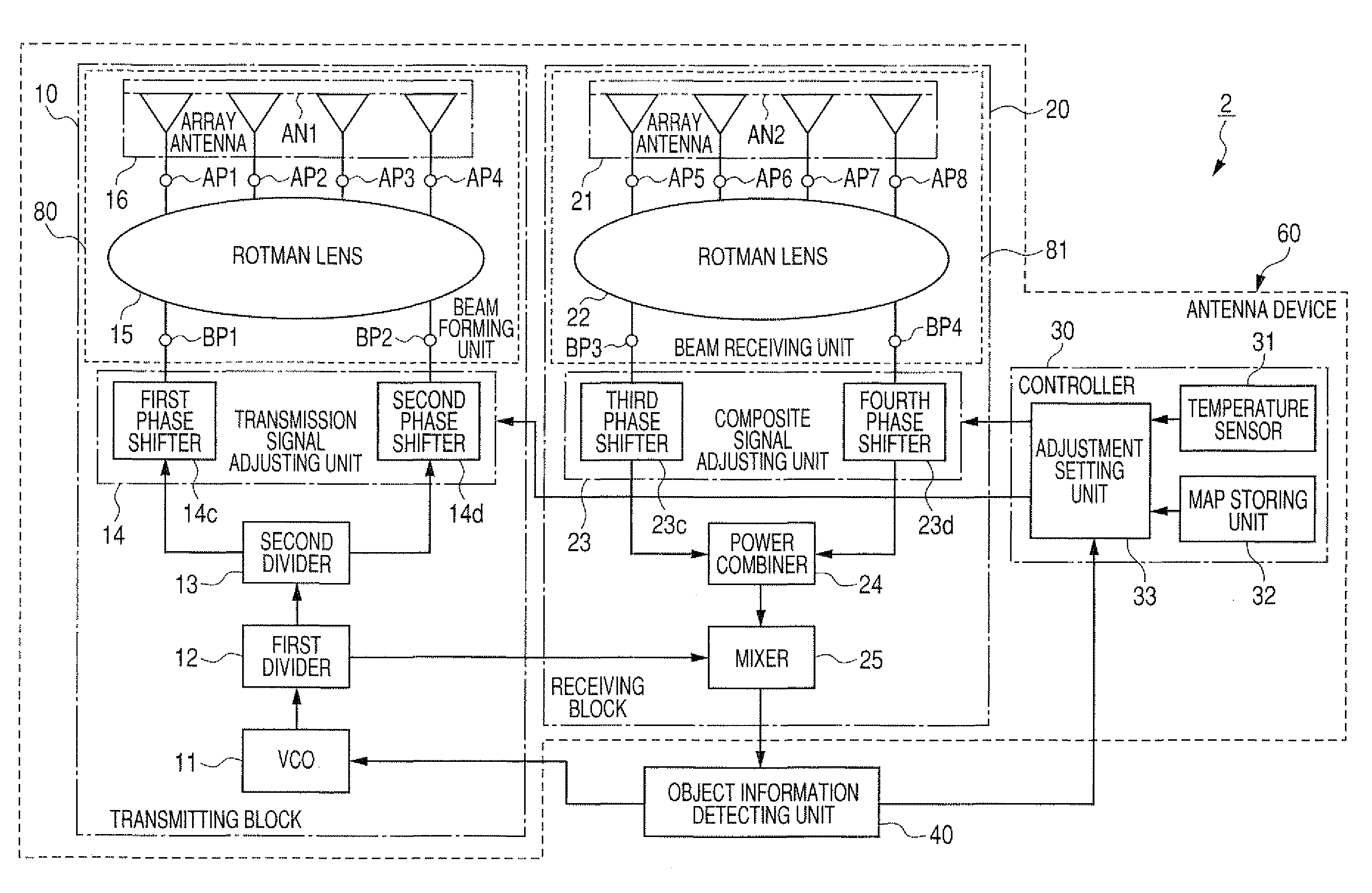
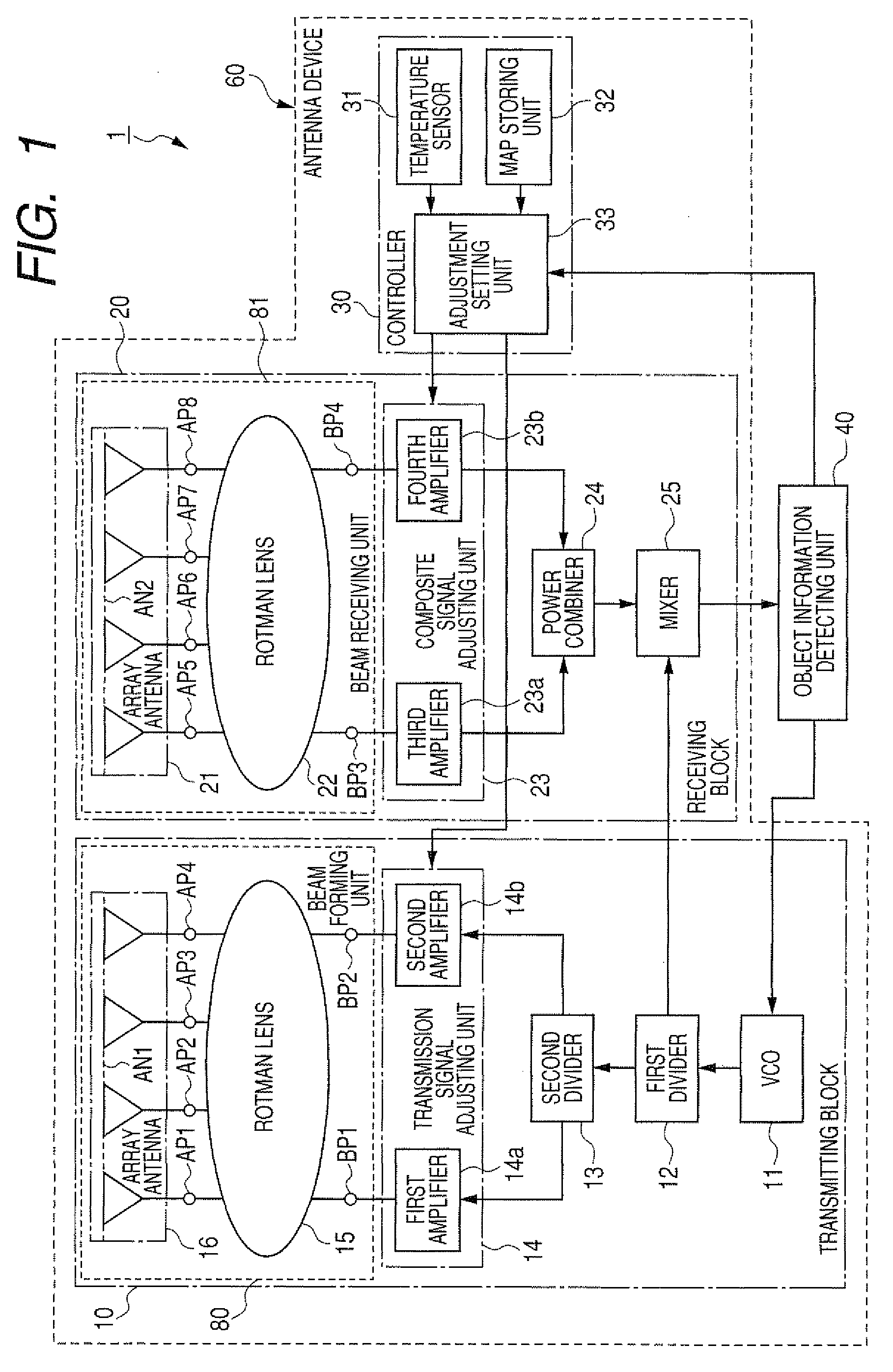
[0043]An antenna device disposed in a radar apparatus will be described. FIG. 1 is a block diagram of a radar apparatus having an antenna device according to the first embodiment.

[0044]As shown in FIG. 1, a radar apparatus 1 has an antenna device 60 for forming and radiating a radar beam and receiving the radar beam from an object, which reflects the radiated beam toward the device 60, and an object information detecting unit 40.

[0045]The antenna device 60 has a transmitting block 10 for transmitting a radar beam of frequency-modulated continuous waves (FMCW) having directivity according to a transmission signal while changing the radiation direction of the beam in a predetermined cycle within a predetermined direction range, a receiving block 20 for receiving the radar beam reflected by the object and producing a reception signal, indicating information about the object, from the received beam, and a beam controller 30 for controlling the transmitting block 10 to adjustably set the...

second embodiment

[0104]FIG. 7 is a block diagram of a radar apparatus having an antenna device according to the second embodiment. As shown in FIG. 7, a radar apparatus 3 differs from the radar apparatus 1 according to the first embodiment in that an antenna device 61 of the radar apparatus 3 has a beam forming unit 82 of a transmitting block 110 in place of the unit 80 and has a beam receiving unit 83 of a receiving block 120 in place of the unit 81.

[0105]The forming unit 82 has a transmission array antenna 17 and a dielectric convex lens 18. The antenna 17 has two antenna elements connected with the respective amplifiers 14a and 14b. The lens 18 has a first input surface (i.e., first input portion) 1a, a second input surface (i.e., second input portion) lab and an antenna surface AN3 acting as an output portion of the unit 82. The antenna elements of the antenna 17 are disposed to be symmetric to each other with respect to the optical axis (i.e., center axis) of the lens 18. These antenna elements...

third embodiment

[0119]FIG. 9 is a block diagram of a radar apparatus having an antenna device according to the third embodiment. As shown in FIG. 9, a radar apparatus 5 differs from the radar apparatus 1 according to the first embodiment in that an antenna device 62 of the radar apparatus 5 has a transmitting and receiving block 50 in place of the blocks 10 and 20. The block 50 has the VCO 11, the dividers 12 and 13, the adjusting unit 14, a beam forming and receiving unit 84, the adjusting unit 23, the combiner 24 and the mixer 25.

[0120]The unit 84 has a Rotman lens 52 and an array antenna 51. The lens 52 has two transmission beam ports BP (BP1 and BP2), a plurality of antenna ports AP (e.g., four antenna ports AP1, AP2, AP3 and AP4) and two reception beam ports BP (BP3 and BP4). The lens 52 is a passive element acting as a lens. The beam ports BP1 and BP2 (i.e., input portions) are placed on the first side of the lens 52 and are spaced from each other at a predetermined interval. The beam ports B...


PUM


Abstract

An antenna device has a divider producing first and second signals, and amplifiers amplifying the signals at a changeable amplitude ratio of the first signal to the second signal. A Rotman lens gives first phase differences to first high frequency waves, produced from the first amplified signal at an input port and transmitted to output ports, and gives second phase differences to second high frequency waves produced from the second amplified signal at another input port and transmitted to the output ports. An antenna forms a beam composed of electromagnetic waves, having the first phase differences and electric power corresponding to the first amplified signal on an antenna surface, and electromagnetic waves, having the second phase differences and electric power corresponding to the second amplified signal on the antenna surface, and radiates the beam in a particular direction corresponding to the phase differences and the amplitude ratio.

Description

CROSS-REFERENCE TO RELATED APPLICATION[0001]This application is based upon and claims the benefit of priority of the prior Japanese Patent Application 2008-243147, filed on Sep. 22, 2008, so that the contents of which are incorporated herein by reference.BACKGROUND OF THE INVENTION[0002]1. Field of the Invention[0003]The present invention relates to an antenna device which forms a beam having a radiation direction freely set by using a lens or a passive element acting as a lens, radiates the beam in the radiation direction and receives the beam reflected by an object to detect the bearing angle to the object.[0004]2. Description of Related Art[0005]An antenna device has been used to radiate a beam of electromagnetic waves while scanning the beam within a predetermined range of scanning angle. Further, this device receives the beam reflected by an object to detect the bearing angle to the object.[0006]For example, a well-known Rotman lens with a Rotman lens pattern acting as wave-gui...

Claims


Application Information

Patent Timeline
Patent Type & Authority Applications(United States)
IPC IPC(8): H01Q1/00H01Q19/06
CPCH01Q25/008
Inventor FUJITA, AKIHISA
Owner DENSO CORP
Why Eureka
Try Eureka