Movable body apparatus, exposure apparatus, exposure method, and device manufacturing method
a technology of exposure apparatus and body, which is applied in the direction of photomechanical treatment, printing, instruments, etc., can solve the problems of short-term variation of measurement values due to temperature, increased size and weight of the wafer stage which moves holding the wafer, and increased size and weight of the wafer stage. , to achieve the effect of high precision and highly precise exposure of the obj
- Summary
- Abstract
- Description
- Claims
- Application Information
AI Technical Summary
Benefits of technology
Problems solved by technology
Method used
Image
Examples
first modified example
A First Modified Example
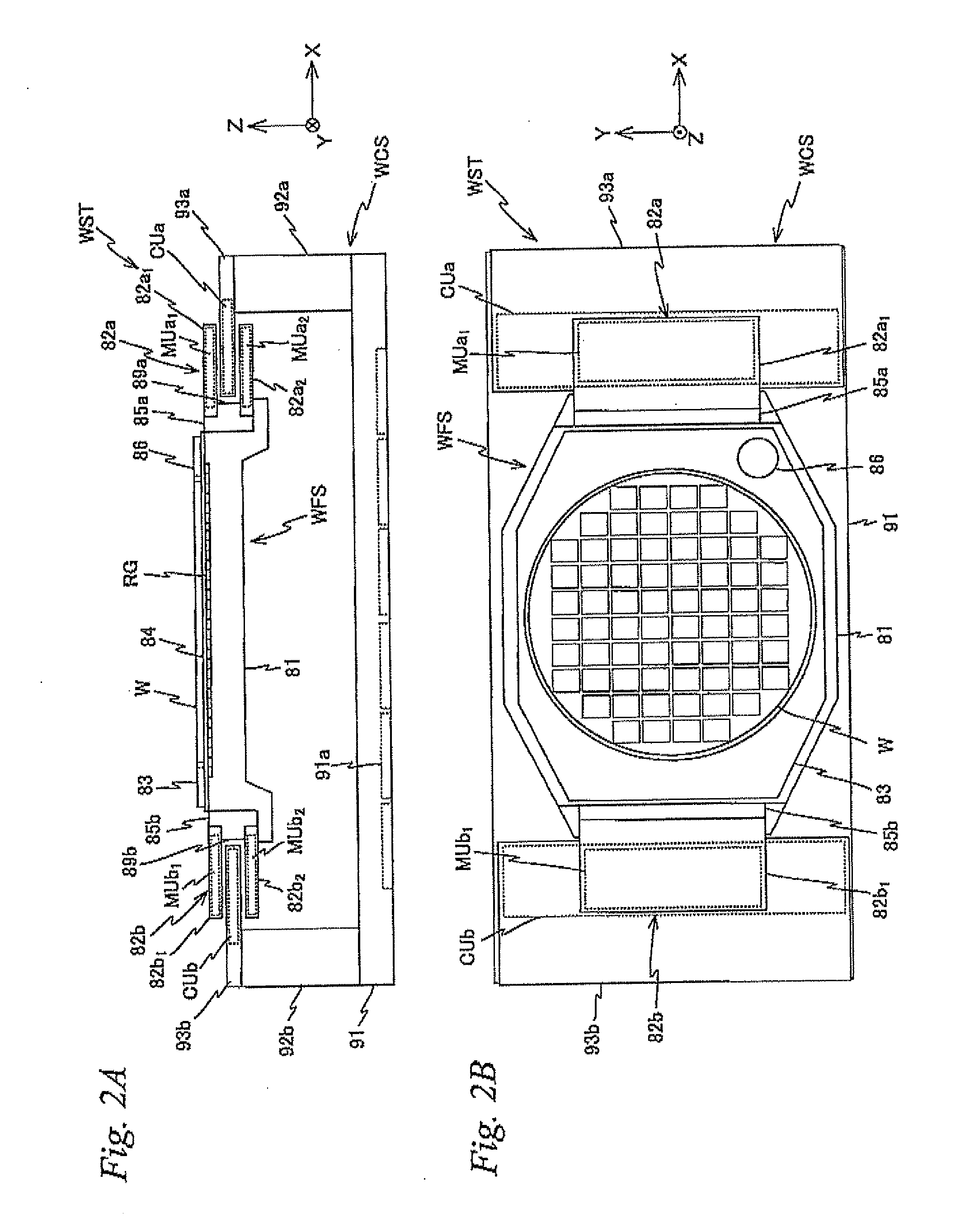
[0154]Incidentally, the configuration of fine movement stage drive system 52 (the first and second drive sections) driving fine movement stage WFS with respect to coarse movement stage WCS is not limited to the one described in the embodiment above. FIG. 16 shows another example of the fine movement stage drive system. In fine movement stage drive system 52 in the embodiment described above, while fine movement stage WFS was driven in Y-axis direction and the Z-axis direction using YZ coils 55 and 57 that were in common, in a fine movement stage drive system 152 shown in FIG. 13, Z drive coils 155 and 158 used exclusively to drive fine movement stage WFS in the Z-axis direction, and a Y drive coil 157 used exclusively to drive fine movement stage WFS in the I-axis direction are provided. In fine movement stage drive system 152, a plurality of first Z drive coils 155 is placed along the Y-axis direction in the vicinity of an end on the −X side inside stator se...
second modified example
A Second Modified Example
[0155]Further, in the embodiment previously described, a configuration can be employed in which fine movement stage WFS and coarse movement stage WCS are relatively movable in the X-axis direction, for example, by the same or a larger distance than the size of a shot area in the X-axis direction on wafer W. In this case, while the configuration of fine movement stage drive system 52 which drives fine movement stage WFS with respect to coarse movement stage WCS is basically the same, a configuration having longer drive strokes in the X-axis direction should be employed. For example, as the pair (two) of permanent magnets 66a1 and 66a2 configuring a part of magnet unit MUa1 and permanent magnets 66b1 and 66b2 configuring a part of magnet unit MUa2, a magnet whose length (width) in the X-axis direction is a length corresponding to a desired drive stroke can be employed, and as X coil 56 configuring a part of coil unit CUa, a coil whose size corresponds to these...
third modified example
A Third Modified Example
[0170]FIG. 17 shows a configuration of an exposure apparatus 1000 related to a third modified example which is equipped with such a second fine movement stage position measurement system. Exposure apparatus 1000 is a twin wafer stage type exposure apparatus which is equipped with an exposure station (an exposure processing section) 200 where projection unit PU is placed, and a measurement station (a measurement processing section) 300 where alignment system. ALG is placed. Here, the same or similar signs will be used for sections the same or similar to exposure apparatus 100 of the first embodiment previously described, and a detailed description thereabout will be omitted or simplified. Further, when there is an equivalent member in both exposure station 200 and measurement station 300, the reference code of each of the members will have a suffix of A and B for identification. However, the reference code of the two wafer stages will be expressed as WST1 and ...
PUM
 Abstract
Description
Claims
Application Information
 - R&D
- Intellectual Property
- Life Sciences
- Materials
- Tech Scout
- Unparalleled Data Quality
- Higher Quality Content
- 60% Fewer Hallucinations
Browse by: Latest US Patents, China's latest patents, Technical Efficacy Thesaurus, Application Domain, Technology Topic, Popular Technical Reports.
© 2025 PatSnap. All rights reserved.Legal|Privacy policy|Modern Slavery Act Transparency Statement|Sitemap|About US| Contact US: help@patsnap.com


