
Solid oxide fuel cell assisted air conditioning system

Inactive Publication Date: 2010-04-01
DELPHI TECH INC
View PDF23 Cites 22 Cited by
  • Summary
  • Abstract
  • Description
  • Claims
  • Application Information

AI Technical Summary

Benefits of technology

[0012]A solid oxide fuel cell (SOFC) system is in communication with the regeneration section of the desiccant wheel providing hot exhaust to drive off moisture adsorbed in the dehumidification section of the wheel. The desiccant wheel transfers moisture from the ambient air to the desiccant material to form a complex compound. The SOFC system supplies hot exhaust air which removes the moisture from the desiccant material by decomposing the complex molecule formed by the adsorbed water vapor and the desiccant material. The SOFC system receives some dehumidified air from the desiccant wheel to perpetuate its cathode reaction. Thus the desiccant wheel and the SOFC system mutually benefit each other resulting in an overall energy efficient air conditioning system.
[0013]The present system provides three distinct modes of operation of the air conditioning system namely summer time comfort cooling and dehumidification, winter time comfort heating and humidification and evaporative cooler drying to ward off any mold growth in the evaporative cooler during long periods of non operation. It improves energy efficiency by more efficiently using the waste heat generated by the SOFC system while simultaneously enhancing the durability of the SOFC system by supplying dry air to the SOFC cathode. Furthermore, the system effectively provides the appropriate level of humidity for the conditioned space both during summer time cooling and winter time heating.

Problems solved by technology

The most common air conditioning system for comfort heating is the fuel-fired system, which is quite energy efficient, but is incapable of providing comfort cooling.
The most common air conditioning system capable of providing both comfort heating and cooling is the heat pump system, which like vapor compression system uses electric power to drive the compressor and as such is not as energy efficient as the fuel-fired system.

Method used


Image

  • Solid oxide fuel cell assisted air conditioning system
  • Solid oxide fuel cell assisted air conditioning system
  • Solid oxide fuel cell assisted air conditioning system

Examples


Embodiment Construction

[0022]Referring to the Figures, wherein like numerals indicate corresponding parts throughout the several views, an air conditioning system is generally shown in FIGS. 6 and 7. The system includes three main components, namely, a desiccant wheel 20, an evaporative cooler 22 and a SOFC system 24, shown in FIG. 5. The system operates in both a comfort heating and humidifying mode, shown in FIG. 6 and a comfort cooling and dehumidifying mode, shown in FIG. 7. The three main components of the air conditioning system namely a desiccant wheel 20, an indirect evaporative cooler 22 and a SOFC system 24 are described first followed by a description of the comfort heating and cooling system.

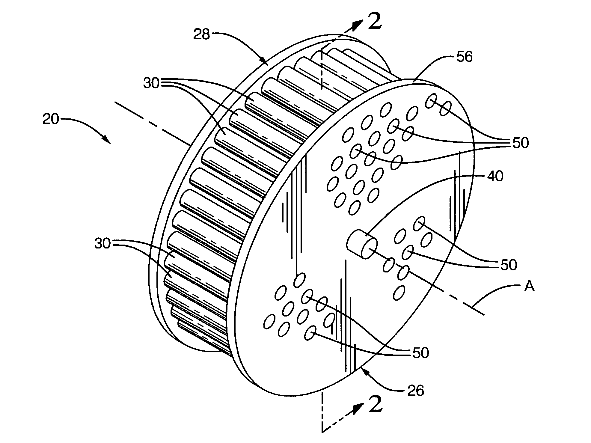
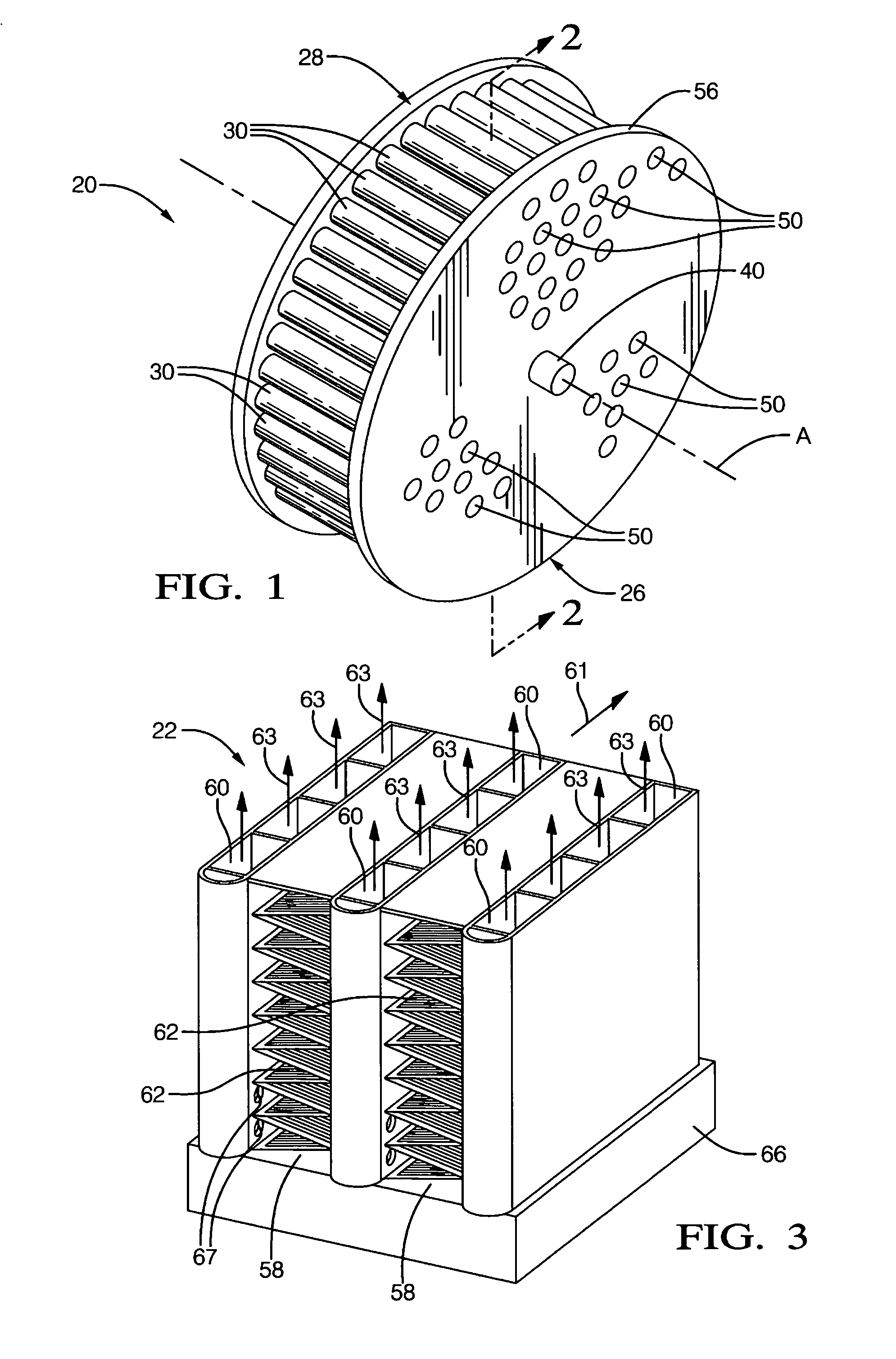
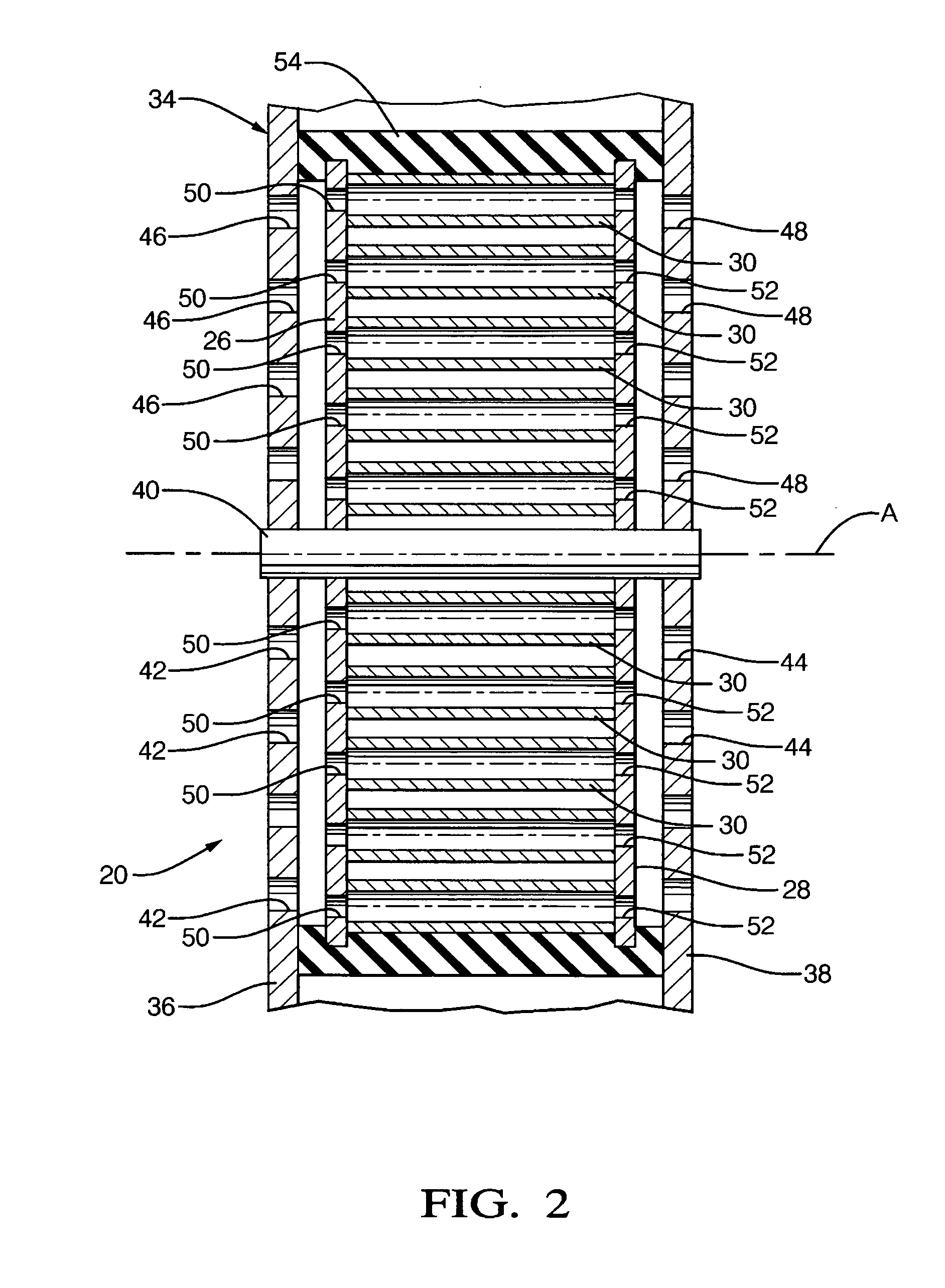
[0023]The desiccant wheel 20, which is shown in FIG. 1, includes an inlet plate 26 and an outlet plate 28 each extending radially about an axis A and having a circular periphery defining a wheel diameter. The plates 26, 28 are in parallel relationship with one another. The desiccant wheel 20 includes a plu...


PUM


Abstract

A housing rotatably supports a desiccant wheel, Ambient air passes through one part of the housing and hot exhaust air passes through the other part. As the wheel rotates, it absorbs moisture from the ambient air in part of the housing and desorbs moisture into the exhaust air in the other part. A fuel cell system supplies the hot exhaust air directly to the desiccant wheel, The dry ambient air is directed to an evaporative cooler and divided between dry channels and wet channels, The air passing through the dry channels cools to be directed to a conditioned space. The air passing through the wet channels evaporates water in the channels facilitating heat transfer and adding moisture to that air. The air from the wet channels is optionally added back into the air from the dry channels to provide appropriate humidity.

Description

BACKGROUND OF THE INVENTION[0001]1. Field of the Invention[0002]An air conditioning system for comfort cooling, heating, humidification and dehumidification of air.[0003]2. Description of the Prior Art[0004]In a broad sense, the term air conditioning refers to heating, cooling, humidification, dehumidification as well as cleaning of air for comfort and other purposes. The subject invention is directed at four-season air conditioning of commercial and residential buildings. The most dominant air conditioning system for comfort cooling is the vapor compression system, which uses electric power to drive the compressor. It is not intended to provide comfort heating. The most common air conditioning system for comfort heating is the fuel-fired system, which is quite energy efficient, but is incapable of providing comfort cooling. The most common air conditioning system capable of providing both comfort heating and cooling is the heat pump system, which like vapor compression system uses ...

Claims


Application Information

Patent Timeline
IPC IPC(8): F25D21/00F28F3/14H01M8/10F24H3/02H01M8/04
CPCF24D5/00Y02E60/525F24F3/1423F24F2203/1032F24F2203/1056F24F2203/1068H01M8/04014H01M8/04022H01M8/04171H01M8/04395H01M8/04425H01M8/04828H01M8/04835H01M8/0612H01M2008/1293H01M2250/00H01M2250/10Y02E60/50Y02B90/14F24D2200/22Y02B90/10
Inventor BHATTI, MOHINDER S.O'BRIEN, JOHN F.REYZIN, ILYAGRIEVE, MALCOLM J.KELLY, SEAN M.
Owner DELPHI TECH INC
Learn More