

Production of an iron powder commodity
a technology of iron powder and commodity, which is applied in the direction of transportation and packaging, process efficiency improvement, metal-working apparatus, etc., can solve the problem of not being able to recover valuable iron-bearing particles as powder, and achieve the effect of removing undesirable emissions into the atmospher
- Summary
- Abstract
- Description
- Claims
- Application Information
AI Technical Summary
Benefits of technology
Problems solved by technology
Method used
Image

Examples
example 1
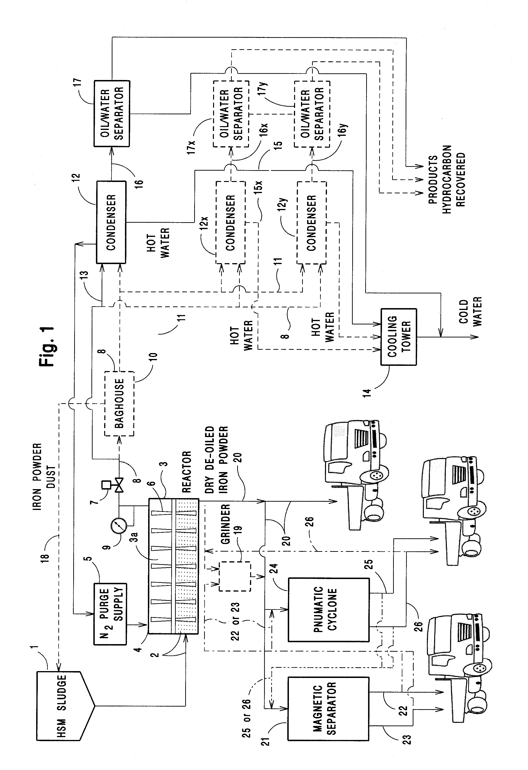
[0035]In the event the HSM mixture 2 comprises certain amounts of nanoparticle and ultrafine particle iron-bearing solids, water, and a particular single hydrocarbon, for example a light oil, a single heating cycle raises the chamber temperature through a temperature range that includes the steam surge temperature and a target temperature suitable for vaporizing the single hydrocarbon, in this instance 550° F. (288° C.) for the light oil. As the chamber temperature is elevated from ambient temperature to the target temperature, the above-mentioned steam surge removes any oil clinging to the solid particle surfaces. As the temperature approaches target temperature, the light oil begins to vaporize, and complete vaporization of the oil is realized at target temperature. The heating cycle is discontinued when the CEM 9 indicates that there are no hydrocarbon vapors evolving from the heated mixture. The reactor vessel 3 is then purged with hot nitrogen gas from supply 5 and the condensa...
example 2
[0036]When HSM sludge 2 comprises certain amounts of nanoparticle and ultrafine particle iron-bearing solids, water, and two or more particular hydrocarbons, i.e. light oil and grease from rolling mill stands, the de-oiling process includes a first and a second heating cycle. The first heating cycle includes the temperature that generates the steam surge within the oily mixture to free sticky or viscid hydrocarbons from the solid particle surfaces, and a lowest, or first, effective temperature for vaporizing one of the hydrocarbons contained in the oily mixture. In this instance, the first effective temperature is an exemplary 550° F. (288° C.), the boiling point temperature for the light oil. The off-gas is fed to condenser 12, and the condensate is fed along line 16 to a separator 17 where it is separated into water and a light oil or first hydrocarbon product. When the CEM 9 indicates an absence of hydrocarbon vapors in the off-gas, chamber 3a is purged with hot nitrogen gas to r...
example 3
[0038]Where HSM sludge 2 comprises certain amounts of nanoparticle and ultrafine particle iron-bearing solids, water, and at least three different hydrocarbons, for example light oil, heavy oil, and grease, the de-oiling process comprises at least three heating cycles. The first heating cycle is operated to raise the chamber temperature through the steam surge temperature range to the lowest effective temperature for vaporizing one of the hydrocarbons contained in the oily mixture as heretofore described above Example 2.
[0039]After the first heating cycle, condensate is separated into water and a first hydrocarbon product using condenser 16 and separator 17, chamber 3a is purged with hot nitrogen, and a second or next successive heating cycle step raises the chamber 3a temperature to a next higher effective temperature for vaporizing one the hydrocarbons contained in the oily mixture. In this example, the chamber temperature is raised to the predetermined boiling point temperature f...
PUM
| Property | Measurement | Unit |
|---|---|---|
| particle size | aaaaa | aaaaa |
| temperature | aaaaa | aaaaa |
| temperature | aaaaa | aaaaa |
Abstract
Description
Claims
Application Information