Method and system for scanning apertureless fluorescence microscope

a fluorescence microscope and scanning aperture technology, applied in the field of high resolution microscopy techniques, can solve the problems of limited resolution ability of such far field optical microscopy, subwavelength aperture techniques that create other limitations, and may still exist certain practical limitations, etc., to achieve the effect of improving resolution, narrow transmission width and convenient us

Inactive Publication Date: 2005-10-11
CALIFORNIA INST OF TECH
View PDF6 Cites 26 Cited by
  • Summary
  • Abstract
  • Description
  • Claims
  • Application Information

AI Technical Summary

Benefits of technology

[0023]In an alternative specific embodiment, the invention provides a scanning microscope for viewing one or more features of molecular scale and below. The system has a support stage for holding an object to be observed. A tip is coupled to a probe, which is configured within a vicinity of a feature of the object. An illumination source is directed to apply electromagnetic radiation from the illumination source to the tip of the probe. This illumination is used to determine the position of the cantilever tip over the sample. The system has a filter coupled to the object to substantially eliminate amplified spontaneous emission (ASE) from a power spectrum of the electromagnetic radiation. Preferably, such filter has a narrow transmission width to block ASE at wavelengths both shorter and longer than a central laser wavelength according to a specific embodiment. Alternately, such filter can be a long pass filter to block ASE with wavelengths shorter than the central laser wavelength. In an alternative embodiment, such filter can be a short pass to block ASE with wavelengths longer than the laser wavelengths longer than the central laser wavelength. The system also has an object illumination source coupled to the support to illuminate at least the feature of the object. Additional filters allow the block

Problems solved by technology

The resolving ability of such far field optical microscopy is generally limited by the diffraction of light.
Such subwavelength aperture techniques create other limitations.
Here, physical limitations relate to a skin depth of the metal used to coat the waveguide and various scanning artifacts,

Method used


Image

  • Method and system for scanning apertureless fluorescence microscope
  • Method and system for scanning apertureless fluorescence microscope
  • Method and system for scanning apertureless fluorescence microscope

Examples


Embodiment Construction

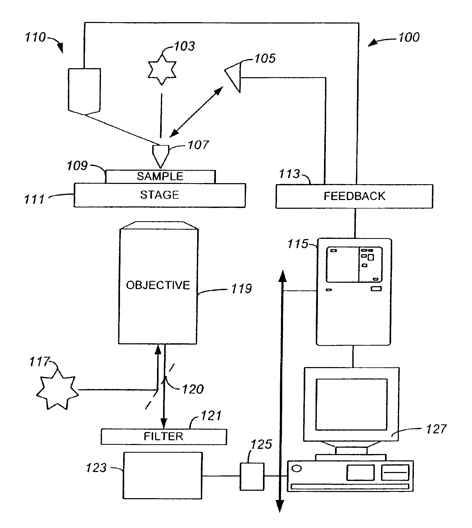
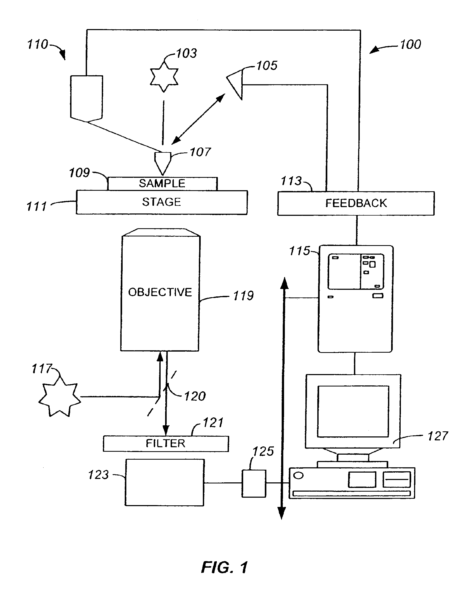
[0042]According to the present invention, techniques for high resolution scanning are provided. More particularly, the invention provides methods and systems for improved high resolution scanning using apertureless near field scanning microscopes that image one or more fluorescent samples with single photon excitation, which we call fluorescence ANSOM microscope. But it would be recognized that the invention has a much broader range of applicability. For example, the invention can be applied with other types of images such as Raman scattering, multiphoton imaging techniques, and others. Additionally, the samples can be from a variety of different fields such as electronics, semiconductor, organic chemistry, life sciences, biotechnology, and others.

[0043]FIG. 1 is a simplified diagram of a scanning system 100 according to an embodiment of the present invention. This diagram is merely an example, which should not unduly limit the scope of the claims herein. One of ordinary skill in th...


PUM


Abstract

Methods and systems for operating an apertureless microscope for observing one or more features to a molecular sensitivity on objects are described. More particularly, the method includes moving a tip of a probe coupled to a cantilever in a vicinity of a feature of a sample, which emits one or more photons at a detected rate relative to a background rate of the sample based upon the presence of the tip of the probe in the vicinity of the feature. The method modifies the detected rate of the feature of the sample, whereupon the modifying of the detected rate causes the feature of the sample to enhance relative to background rate of the feature.

Description

CROSS-REFERENCES TO RELATED APPLICATIONS[0001]This application claims priority to U.S. Provisional No. 60 / 402,351 filed Aug. 9, 2002, which is incorporated by reference herein.STATEMENT AS TO RIGHTS TO INVENTIONS MADE UNDER FEDERALLY SPONSORED RESEARCH OR DEVELOPMENT[0002]The U.S. government has rights in the disclosed invention pursuant to National Science Foundation Grant No. DMR-0080065 to the California Institute of Technology.REFERENCE TO A “SEQUENCE LISTING,” A TABLE, OR A COMPUTERPROGRAM LISTING APPENDIX SUBMITTED ON A COMPACT DISK[0003]Not ApplicableBACKGROUND OF THE INVENTION[0004]The present invention relates generally to high resolution microscopy techniques. More particularly, the invention provides methods and systems for improved high resolution scanning using apertureless near field scanning optical microscopes (“ANSOM”) that image one or more fluorescent samples with single photon excitation, which we call fluorescence ANSOM (“FANSOM”). But it would be recognized tha...

Claims


Application Information

Patent Timeline
IPC IPC(8): G02B21/16G01Q30/02G01Q30/04G01Q30/18G01B11/30G01Q40/00G01Q60/06G01Q60/20G01Q70/12G02B21/00
CPCB82Y10/00B82Y15/00B82Y20/00B82Y35/00G01Q30/04G01Q30/18G01Q40/00G01Q60/06G01Q60/20G01Q70/12G02B21/16G01Q30/025Y10S977/862
Inventor QUAKE, STEPHEN R.LESSARD, GUILLAUMEWADE, LAWRENCE A.GERTON, JORDAN M.
Owner CALIFORNIA INST OF TECH
Why Eureka
Try Eureka