
Method for weld-joining attachment to outer panel of railway vehicle and car body side structure produced by the same

a technology of railway vehicles and attachments, which is applied in the direction of window arrangements, manufacturing tools, transportation and packaging, etc., can solve the problems of deterioration of appearance, increased cost, and increased cost, so as to reduce the number improve workability. , the effect of increasing the ratio of long horizontal frame members

Active Publication Date: 2010-04-01
KINKI SHARYO
View PDF7 Cites 13 Cited by
  • Summary
  • Abstract
  • Description
  • Claims
  • Application Information

AI Technical Summary

Benefits of technology

[0007]In the structure described in Patent Document 1, since the vertical and horizontal frame members are laser welded to the outer panel, the formation of the linear mark g on the decorative surface can not be avoided. In addition, the horizontal frame members are divided by the vertical frame members, so that the welding cannot be performed in a continuous manner. In view of the above, the present inventor has completed an inventive method for weld-joining attachments to an outer panel of a railway vehicle, in which the outer panel having polishing marks formed in a specific direction is used. The present inventor has also completed a car body side structure produced by the method. The method and the car body side structure are advantageous in terms of appearance, workability, and cost.
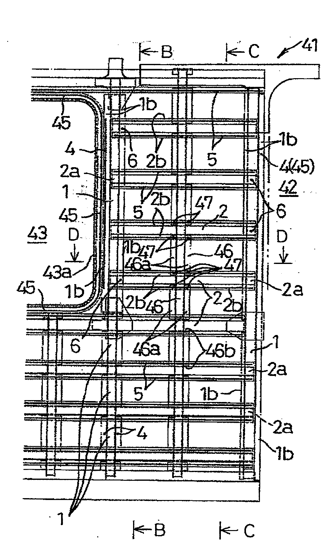
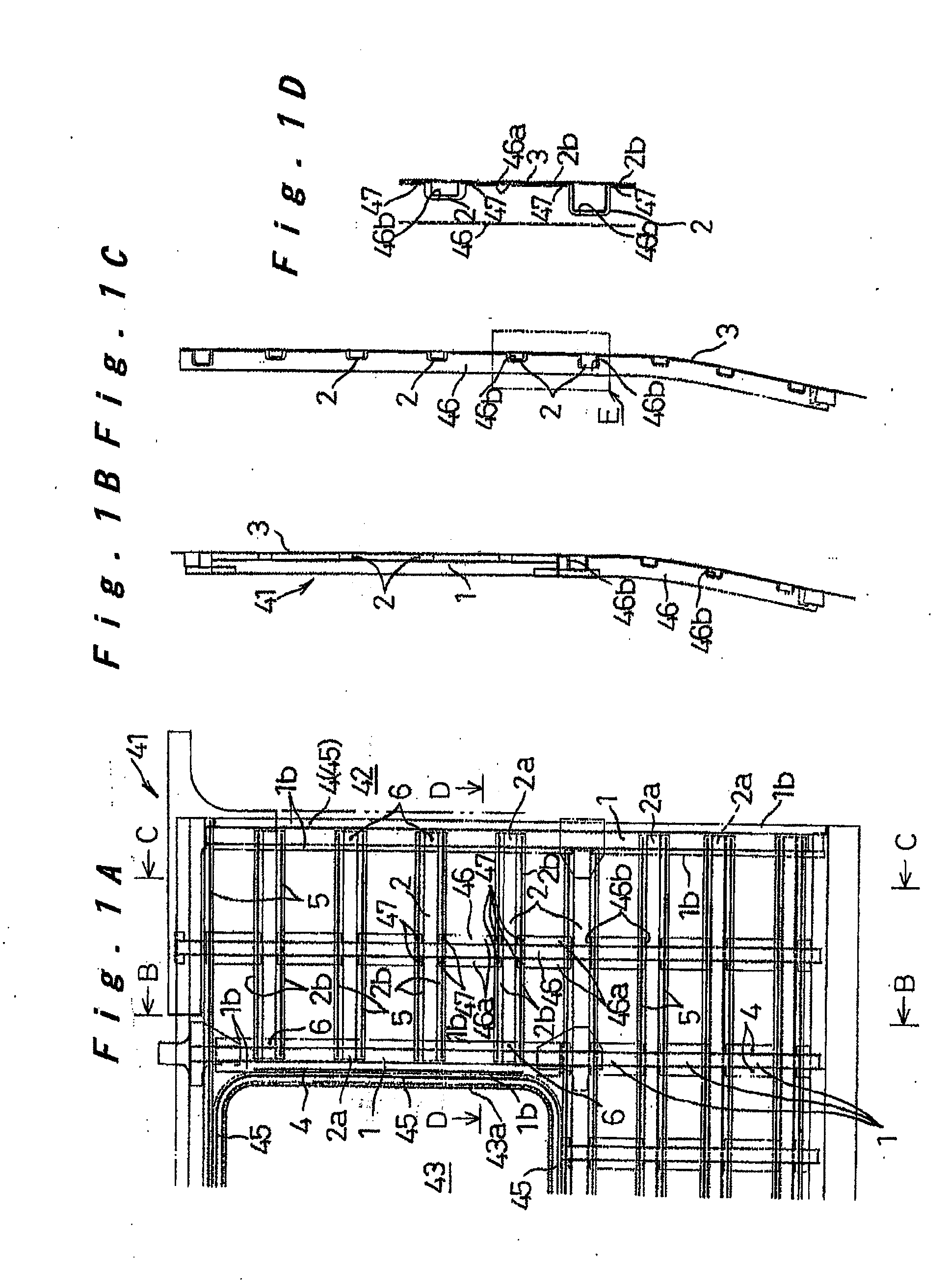
[0015]In another configuration, the outer panel includes an opening for a window and an opening for an entrance door. The horizontal frame members are disposed at substantially regular vertical intervals on the interior surface of the outer panel except for the openings for the window and the entrance door. The vertical frame members are disposed along side portions of the openings for the window and the entrance door and along an end portion of the outer panel. Between the vertical frame members, a vertical reinforcing member is placed on the horizontal frame members from an interior side so as to extend therebetween and is joined thereto at weld-joining portions welded by any of plug welding, spot welding, and laser welding. In this case, in areas where the horizontal frame members can be disposed, a higher priority is given to the horizontal frame members than to the vertical frame members so that the number of the horizontal frame members disposed in those areas is greater than the number of the vertical frame members. In this manner, the horizontal frame members are prevented from being divided by the vertical frame members, and the continuity of laser welding is maintained. Therefore, the required car body strength can be ensured by the vertical frame members significantly reduced in their number and by the vertical reinforcing members that can be weld-joined by any suitable one of various welding methods without affecting the outer panel and the appearance. Specifically, the reinforcing members are not welded to and not in contact with the outer panel while they are arranged in a separating state with respect to the outer panel. Therefore, the strength to resist out-of-plane deformation caused by the in-plane shear force in the outer panel can be improved.

Problems solved by technology

However, since a load of 1 t is applied during the spot welding process, indentations are formed on the exterior surface, resulting in the deterioration of the appearance.
In addition, much time and labor are required for joining, and the cost increases.
Since a large load is applied, a large apparatus is required, and an expensive copper-made electrode plate d must be used, so that the cost for the equipment is high.

Method used


Image

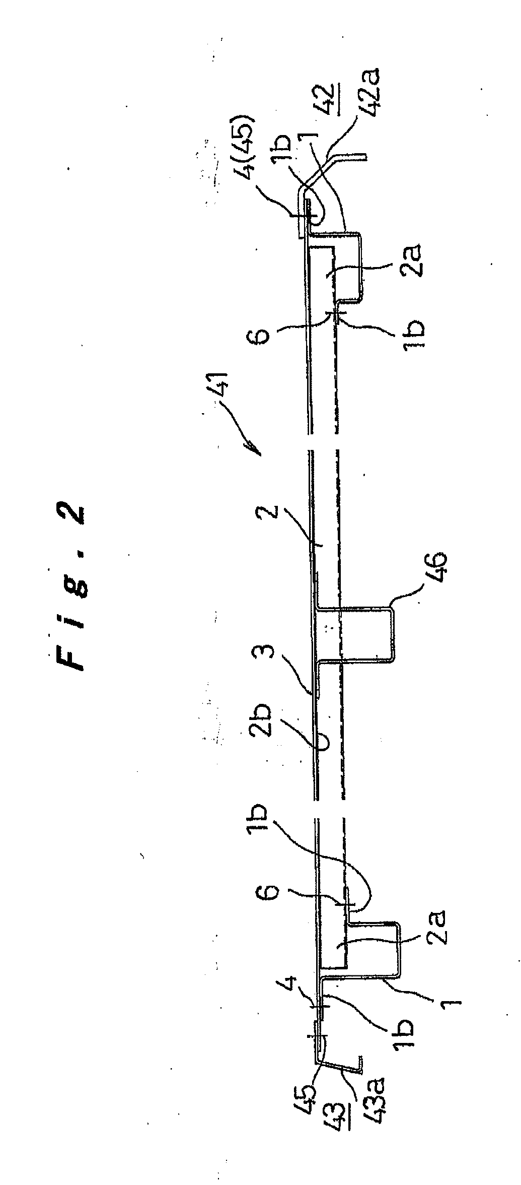
  • Method for weld-joining attachment to outer panel of railway vehicle and car body side structure produced by the same
  • Method for weld-joining attachment to outer panel of railway vehicle and car body side structure produced by the same
  • Method for weld-joining attachment to outer panel of railway vehicle and car body side structure produced by the same

Examples


Embodiment Construction

[0025]With reference to FIGS. 1A to 4B, an embodiment of a method for weld-joining attachments to an outer panel of a railway vehicle according to the present invention and an embodiment of a car body side structure produced by the inventive method are specifically described to facilitate understanding of the invention.

[0026]In one embodiment, a car body side structure 41 shown in FIGS. 1A to 1D and 2 is produced. Specifically, attachments are weld-joined to a stainless steel-made outer panel 3 shown in FIG. 2. The attachments include: stainless steel-made frame members 1 and 2 vertically and horizontally arranged to reinforce the outer panel 3; and stainless steel-made opening frames and opening frame members 42a and 43a used as exterior members disposed on opening edges for an entrance door 42 and a window 43. However, the present invention is not limited to the above embodiment and is applicable to any car body structure including an outer panel of a railway vehicle and attachmen...


PUM

PropertyMeasurementUnit
thicknessaaaaaaaaaa
thicknessaaaaaaaaaa
penetration depthaaaaaaaaaa

Abstract

A weld-joining structure between an outer panel and an attachment is achieved, which is advantageous in terms of appearance, workability, and cost. To weld-join the outer panel and the attachments including, such as frame members and opening frames and opening frame members, which is a reinforcement or an interior or exterior member for use in the outer panel, the outer panel and the attachment placed on the outer panel are weld-joined by laser welding at overlapping portions of the outer panel and the attachment. The laser welding is performed along a polishing mark formed in one direction on an externally exposed-side surface of the outer panel and the attachment.

Description

TECHNICAL FIELD[0001]The present invention relates to a method for weld-joining an attachment to an outer panel of a railway vehicle. In particular, the invention relates to a method for weld-joining an attachment to an outer panel of a railway vehicle, the method being carried out such that the attachment, such as a frame member, an opening frame, and an opening frame member, which is a reinforcement or an interior or exterior member for use in the outer panel, is weld-joined to the outer panel. The invention also relates to a car body side structure produced by the method.BACKGROUND ART[0002]In one known structure for reinforcing an outer panel of a railway vehicle, vertically and horizontally arranged frame members are placed on and weld-joined to the interior surface of the outer panel to reinforce the outer panel (see, for example, Patent Document 1). In another exemplary structure, vertical and horizontal frame members b and c are disposed on and weld-joined to an outer panel ...

Claims


Application Information

Patent Timeline
Patent Type & Authority Applications(United States)
IPC IPC(8): B61D17/08B61D17/00B61D25/00B23K26/20
CPCB23K26/246B61D17/08B23K2201/006B23K31/02B23K26/244B23K2101/006
Inventor HARADA, HIROJIKONO, YOSHINORISUMIKAWA, TOMONORIYONETANI, HIROSHITANAKA, YASUHIROKATO, EIICHI
Owner KINKI SHARYO
Learn More