Air-fuel ratio control device of internal combustion engine

a technology of air-fuel ratio and control device, which is applied in the direction of electrical control, machine/engine, exhaust treatment electric control, etc., can solve the problems of excessive purification rate of nox, and excessive oxygen occlusion quantity of the catalyst, so as to reduce the lean disturbance rate and improve the purification rate quickly , the effect of high precision

Inactive Publication Date: 2010-04-01
DENSO CORP
View PDF3 Cites 11 Cited by
  • Summary
  • Abstract
  • Description
  • Claims
  • Application Information

AI Technical Summary

Benefits of technology

[0016]It is an object of the present invention to provide an air-fuel ratio control device of an internal combustion engine capable of efficiently reducing NOx emission quantity when a lean disturbance occurs and efficiently purifying a rich component when a rich disturbance occurs after the occurrence of the lean disturbance.
[0017]It is another object of the present invention to provide an air-fuel ratio control device of an internal combustion engine capable of precisely modifying change of a behavior of sub correction quantity (correction quantity defined by sub feedback control) and efficiently purifying exhaust gas with a catalyst.

Problems solved by technology

If the air-fuel ratio of the exhaust gas flowing into the catalyst becomes lean due to fuel cut, oxygen occlusion quantity of the catalyst becomes excessive, so a purification rate of NOx (as a lean component) lowers.
If a lean disturbance, which causes the air-fuel ratio of the exhaust gas flowing into the catalyst to become lean, occurs as shown in FIG. 21, there is a possibility that the oxygen occlusion quantity of the catalyst becomes excessive and the purification rate of NOx (as the lean component) lowers.
However, if the control is performed to smoothly change the air-fuel ratio downstream of the catalyst in a rich direction (i.e., a direction toward a richer air-fuel ratio) such that the air-fuel ratio converges to the target air-fuel ratio by the air-fuel ratio control as described in above Patent document 1 or Patent document 2 when the lean disturbance occurs, the oxygen occlusion quantity of the catalyst cannot be decreased quickly.
Therefore, when a rich disturbance, which causes the air-fuel ratio of the exhaust gas flowing into the catalyst to become rich, occurs thereafter, there is a possibility that the rich components such as HC and CO cannot be purified efficiently and the exhaust emission worsens.
Therefore, when the rich disturbance occurs thereafter, there is a possibility that the rich components such as HC and CO cannot be purified efficiently and the exhaust emission worsens.
However, there is a possibility that a behavior (an output waveform) of the sub correction quantity changes due to an individual difference or degradation (aging change) of the system (including the catalyst and the sensors).
If the change (deviation) of the behavior of the sub correction quantity due to such the individual difference or degradation of the system enlarges, there is a possibility that the exhaust gas cannot be purified efficiently with the catalyst.
If the control gain or the control parameter is simply changed in accordance with the degradation degree of the catalyst as in the technology of above Patent document 5 or Patent document 6, the change (deviation) of the behavior of the sub correction quantity due to the individual difference or the degradation of the system cannot be modified with high precision, and there is a possibility that the exhaust gas cannot be purified efficiently with the catalyst.

Method used


Image

  • Air-fuel ratio control device of internal combustion engine
  • Air-fuel ratio control device of internal combustion engine
  • Air-fuel ratio control device of internal combustion engine

Examples


first embodiment

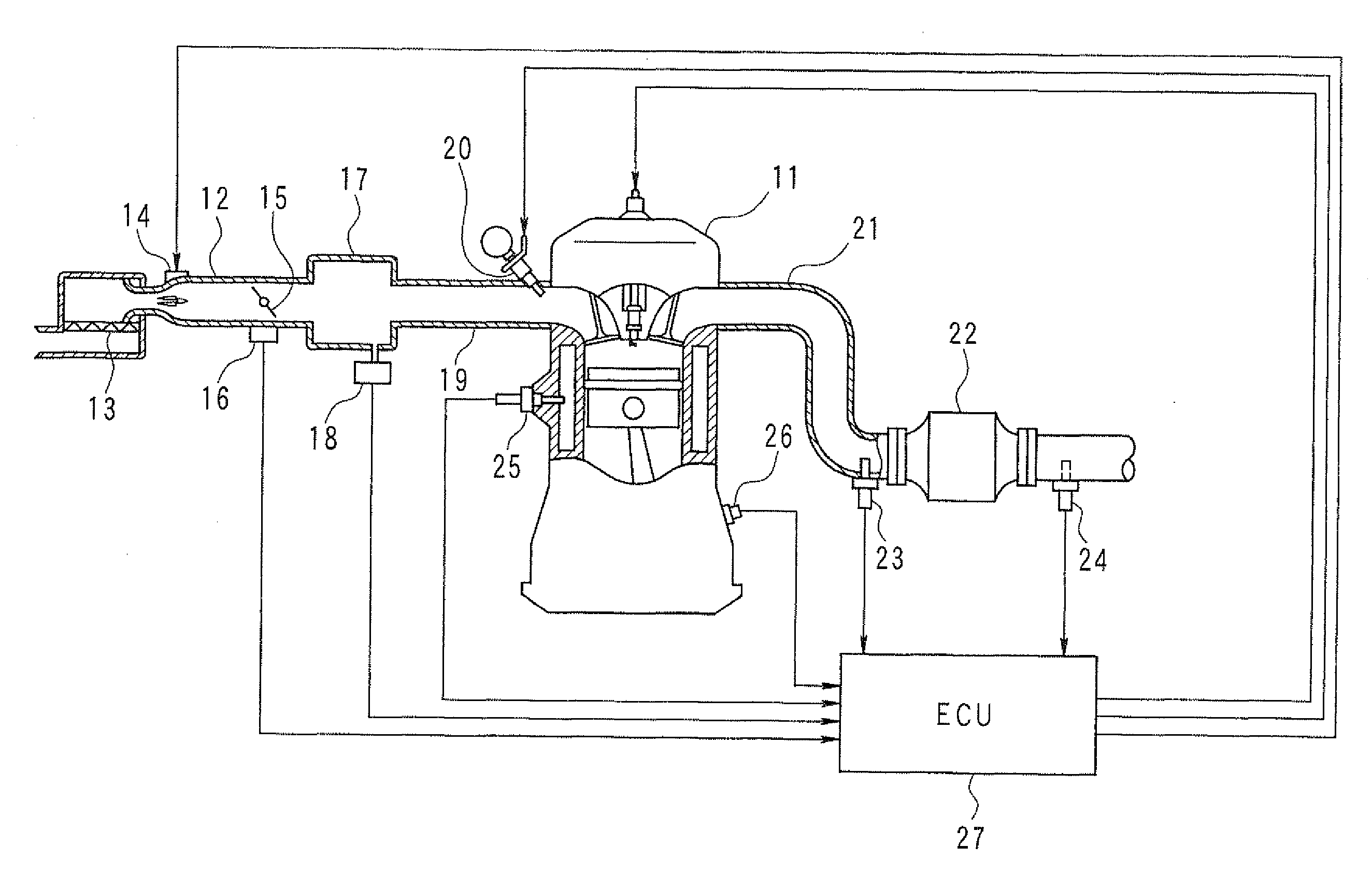
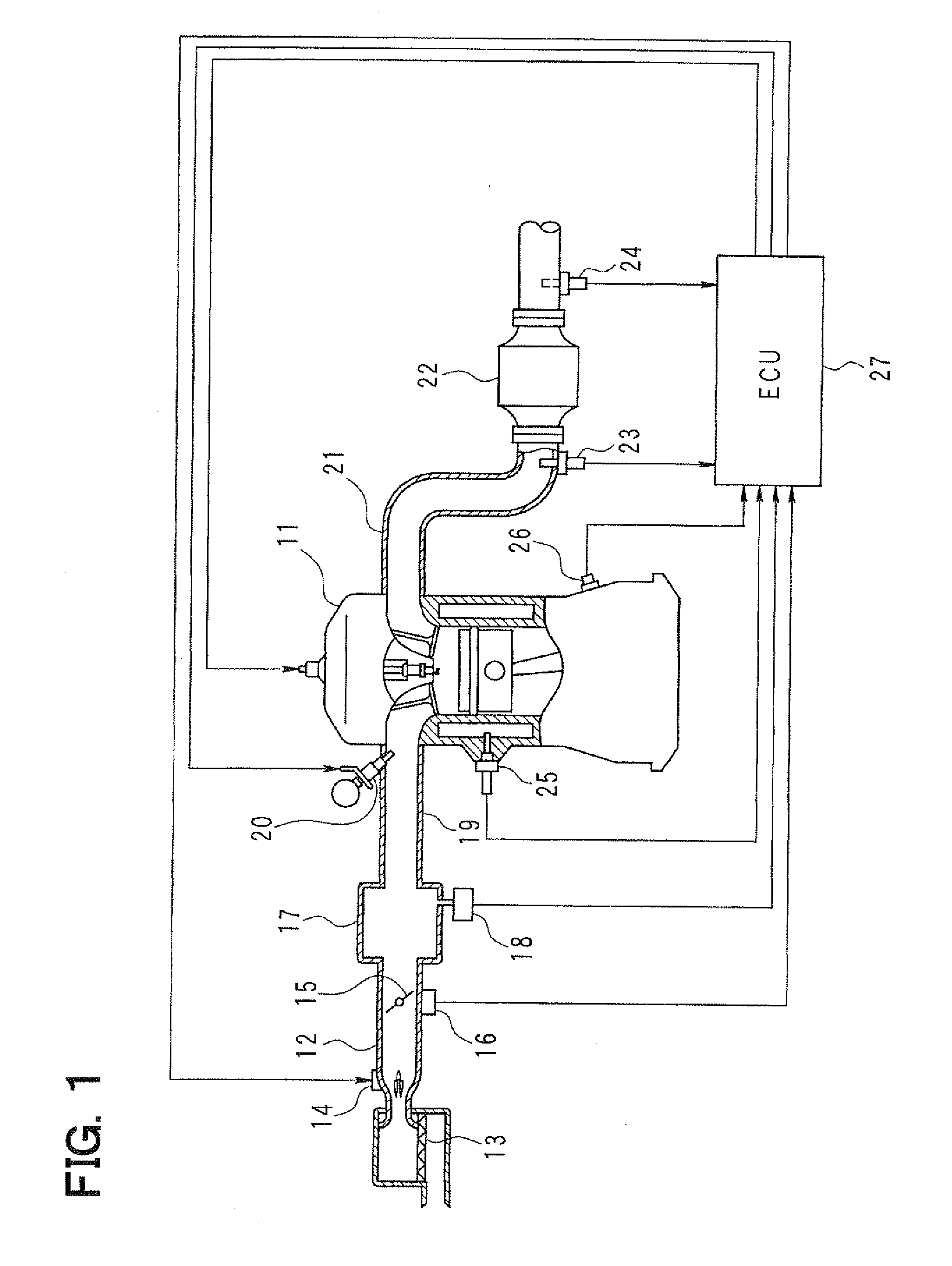
[0055]Hereafter, embodiments of the present invention will be described with reference to the drawings. First, a general configuration of an entire engine control system according to the present invention will be explained with reference to FIG. 1. An air cleaner 13 is provided in a most upstream portion of an intake pipe 12 of an engine 11 (an internal combustion engine). An airflow meter 14 for sensing intake air quantity is provided downstream of the air cleaner 13. A throttle valve 15, whose opening degree is regulated by a motor (not shown), and a throttle position sensor 16 for sensing an opening degree (a throttle opening) of the throttle valve 15 are provided downstream of the airflow meter 14.

[0056]A surge tank 17 is provided downstream of the throttle valve 15, and an intake pipe pressure sensor 18 for sensing intake pipe pressure is provided to the surge tank 17. An intake manifold 19 for introducing an air into each cylinder of the engine 11 is provided to the surge tank...

second embodiment

[0127]Next, an execution example of the control parameter changing processing of the above-described second embodiment will be explained with reference to a time chart of FIG. 19. In the example of FIG. 19, the air-fuel ratio of the exhaust gas flowing into the catalyst 22 changes in the lean direction due to the disturbance or the like while the main feedback control and the sub feedback control are performed in the sate where the engine operation state is stable during the engine operation. As a result, the output A / Fdown of the downstream sensor 24 becomes a leaner value than the leanness determination value THL at a time point t1. The measurement of the sub correction quantity is started at the time point t1. Thereafter, the measurement of the sub correction quantity Qsub is ended at a time point t2 when the output A / Fdown of the downstream sensor 24 converges to the control target value. Thus, the behavior (i.e., the output waveform) of the sub correction quantity Qsub in the p...


PUM


Abstract

When an output of a downstream sensor provided downstream of a catalyst for exhaust gas purification becomes a leaner value than a leanness determination value, an air-fuel ratio control device supplies a rich component to the catalyst by performing rich input processing, in which increase correction for increasing fuel injection quantity stepwise is performed and then increase correction quantity of the fuel injection quantity is decreased gradually. When the increase correction quantity of the fuel injection quantity defined by the rich input processing becomes zero or when oxygen occlusion quantity of the catalyst becomes zero, the control device supplies a lean component to the catalyst by performing lean input processing, in which decrease correction for decreasing the fuel injection quantity stepwise is performed and then decrease correction quantity of the fuel injection quantity is decreased gradually.

Description

CROSS REFERENCE TO RELATED APPLICATION[0001]This application is based on and incorporates herein by reference Japanese Patent Applications No. 2008-255529 filed on Sep. 30, 2008 and No. 2008-255530 filed on Sep. 30, 2008.BACKGROUND OF THE INVENTION[0002]1. Field of the Invention[0003]The present invention relates to an air-fuel ratio control device of an internal combustion engine having a downstream sensor provided downstream of a catalyst, which purifies exhaust gas, for sensing an air-fuel ratio or a rich / lean state of the exhaust gas.[0004]The present invention also relates to an air-fuel ratio control device of an internal combustion engine having sensors provided respectively upstream and downstream of a catalyst, which purifies exhaust gas of the internal combustion engine, each for sensing an air-fuel ratio or a rich / lean state of the exhaust gas.[0005]2. Description of Related Art[0006]Among recent automobile exhaust gas purification systems, there is a system that has sens...

Claims


Application Information

Patent Timeline
Patent Type & Authority Applications(United States)
IPC IPC(8): F02D41/00F02D45/00F01N3/10F01N11/00
CPCF01N3/10F02D41/126F02D41/1441F02D2250/36F02D2041/1418F02D2041/1422F02D2200/0814F02D41/1456
Inventor SAKAMOTO, YURI
Owner DENSO CORP
Why Eureka
Try Eureka