
Hybrid Electric Vehicle Traction Motor Driven Power Take-Off Control System

a technology of electric vehicle and control system, which is applied in the direction of gas pressure propulsion mounting, process and machine control, propulsion parts, etc., can solve the problems of deactivation of hybrid electric traction motor by the epto control system, and achieve the reduction of product variation costs, reducing the need for and complexity of activation signals, and increasing the level of operation efficiency and safety.

Active Publication Date: 2010-04-01
INT TRUCK INTPROP LLC
View PDF8 Cites 33 Cited by
  • Summary
  • Abstract
  • Description
  • Claims
  • Application Information

AI Technical Summary

Benefits of technology

[0004]In order to address the problems described previously, it is beneficial to reduce the number and complexity of the input signal devices associated with the second body manufacturer installed hydraulic equipment, and employ control strategy software residing within the control system of the ePTO which monitors hydraulic main system pressure deltas and simultaneous trend vectors. The control system of the ePTO may reside within the vehicle Electronic System Controller's (ESC) software and hardware input output architecture. The pressure deltas and trend vectors, calculated from pressure signals provided by one or more analog hydraulic pressure transducers, can be employed by the control system to determine the need to generate a continuation of operation signal for the continuation of the hybrid electric traction motor driven PTO's operation. Note that the initiation of the hybrid electric traction motor must come from a secondary equipment manufacturer signal request device connected directly to the ESC or one of the vehicle Remote Power Modules (RPM). The analog hydraulic pressure transducer may be connected to the second body manufacturer hydraulic equipment high pressure hydraulic hose leading from the ePTO driven hydraulic pump to the first hydraulic circuit supplying hydraulic potential to the second body manufacturer installed hydraulic equipment in the case of open center type hydraulic systems. Alternately, the analog hydraulic pressure transducer may be connected to a valve body that exposes the transducer to the hydraulic potential within the second body manufacturer high pressure hydraulic hose leading from the ePTO driven hydraulic pump to the first hydraulic circuit supplying hydraulic potential to the second body manufacturer installed hydraulic equipment by shuttling a valve via return line pressure within the low pressure hydraulic hose leading from the first hydraulic circuit to the reservoir via a transducer sense pressure line in the case of closed center type hydraulic systems. This return line pressure is generated as a consequence of every actuation of the hydraulic equipment. Furthermore, if the second body manufacturer hydraulic equipment is provided with both open center type and closed center type hydraulic systems, an analog hydraulic pressure transducer may be connected to the second body manufacturer hydraulic equipment high pressure hydraulic hose leading from the ePTO driven hydraulic pump to the first hydraulic circuit supplying hydraulic potential to the second body manufacturer installed open center type hydraulic systems, and also may be connected to the high pressure hydraulic hose leading from the ePTO driven hydraulic pump to the first hydraulic circuit and to the low pressure hydraulic hose leading from the first hydraulic circuit to the hydraulic reservoir via a transducer sense pressure line in the closed center type hydraulic systems as will become apparent from the drawings that follow. In this design, one analog hydraulic pressure transducer is capable of sensing hydraulic pressure deltas and trend vectors indicative of normal equipment operation in both open and closed center portions of a combined open and closed center hydraulic type hydraulic system.
[0013]Finally, the control strategy software residing within the control system of the ePTO may be provided with a programmable debounce feature, such that momentary spikes of the red line above 150 psi are ignored for the purposes of system initialization. This prevents impact pressures which are communicated through the hydraulic system to the analog hydraulic pressure transducer from causing unnecessary initializations of the control strategy software residing within the control system of the ePTO and the resulting unnecessary running of the hybrid electric traction motor driven PTO. It is emphasized that the same control strategy software residing within the control system of the ePTO works with open center, closed center, and combined open and closed center hydraulic systems, though the output of the analog hydraulic pressure transducer tends to be square in form on closed center hydraulic systems, and more analog in form on open center hydraulic systems. This provides for commonality of systems and reduced product variation costs.
[0014]Overall, the control strategy software residing within the ePTO control system, and the signals produced by the analog hydraulic pressure transducer, reduce the need for and complexity of activation signals produced by mechanical sourcing devices or switches integrated in conjunction with hydraulic valves, levers or other mechanical electrical switch devices installed by the second body manufacturer. This delivers increased levels operational efficiency and safety for a hybrid system utilizing an ePTO, as well as increased effectiveness in the area of integration between initial vehicle manufacturer and second body manufacturer systems.

Problems solved by technology

However, as long as the ePTO control system continues to detect activity in the hydraulics system indicative of normal equipment operation via the analog hydraulic pressure transducer, the hybrid electric traction motor continues in its active state, even though there may no longer be an active activation signal coming from any of the remaining mechanical input devices.
Once there is no longer any detection by the ePTO control system via the analog hydraulic pressure transducer of any activity in the second body manufacturer hydraulic system indicative of normal equipment operation, and there is no active activation signal from any of the mechanical input devices, a first programmable timer will be allowed to expire, resulting in the deactivation of the hybrid electric traction motor by the ePTO control system.

Method used


Image

  • Hybrid Electric Vehicle Traction Motor Driven Power Take-Off Control System
  • Hybrid Electric Vehicle Traction Motor Driven Power Take-Off Control System
  • Hybrid Electric Vehicle Traction Motor Driven Power Take-Off Control System

Examples


Embodiment Construction

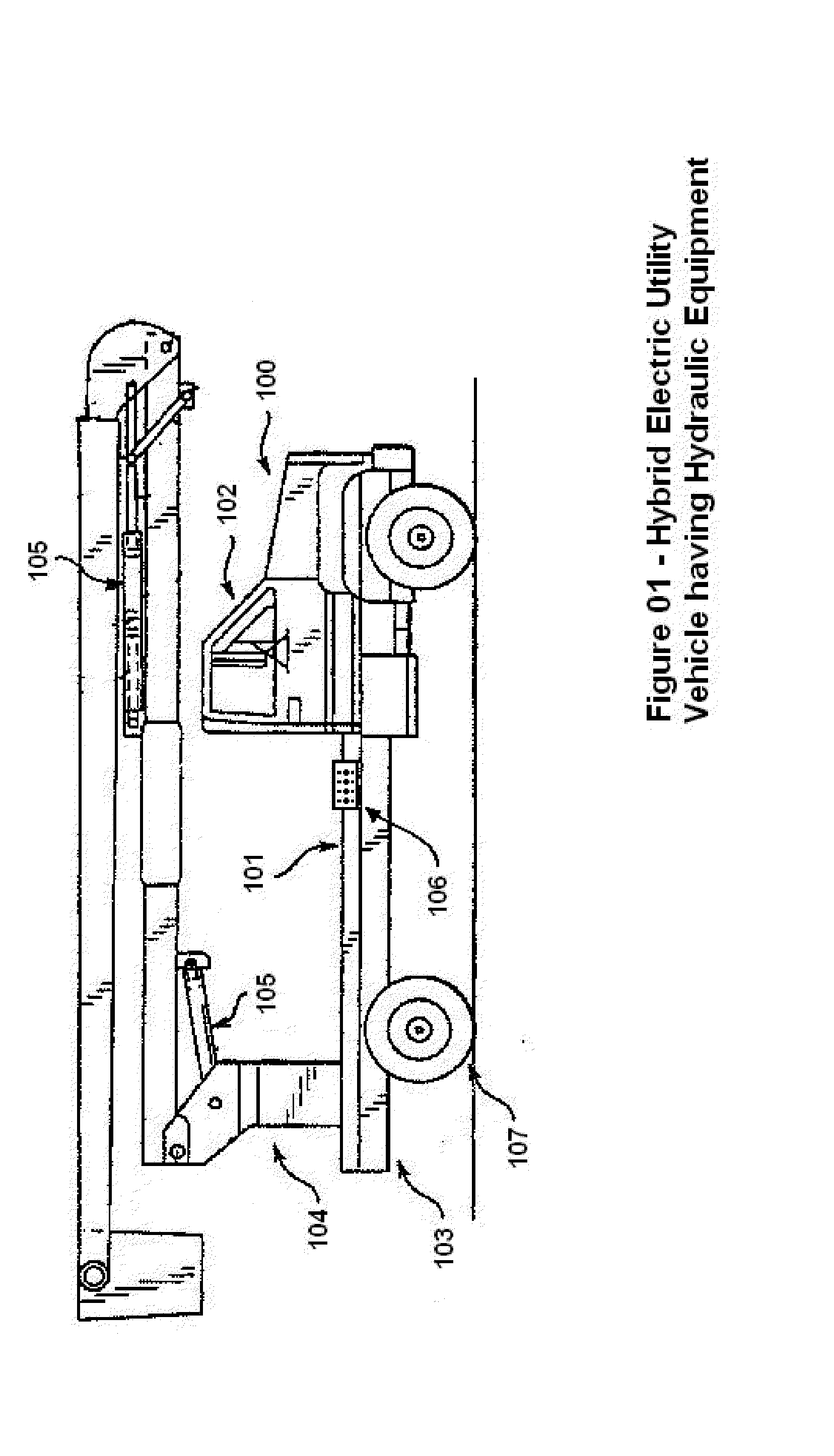
[0030]FIG. 1 shows a vehicle 100 having a body 101, a cab 102, a chassis 103, and running gear 107. The body 101 is provided with body equipment 104 which is operated by means of hydraulic actuators 105. Mechanical input devices 106 control the hydraulic actuators 105.

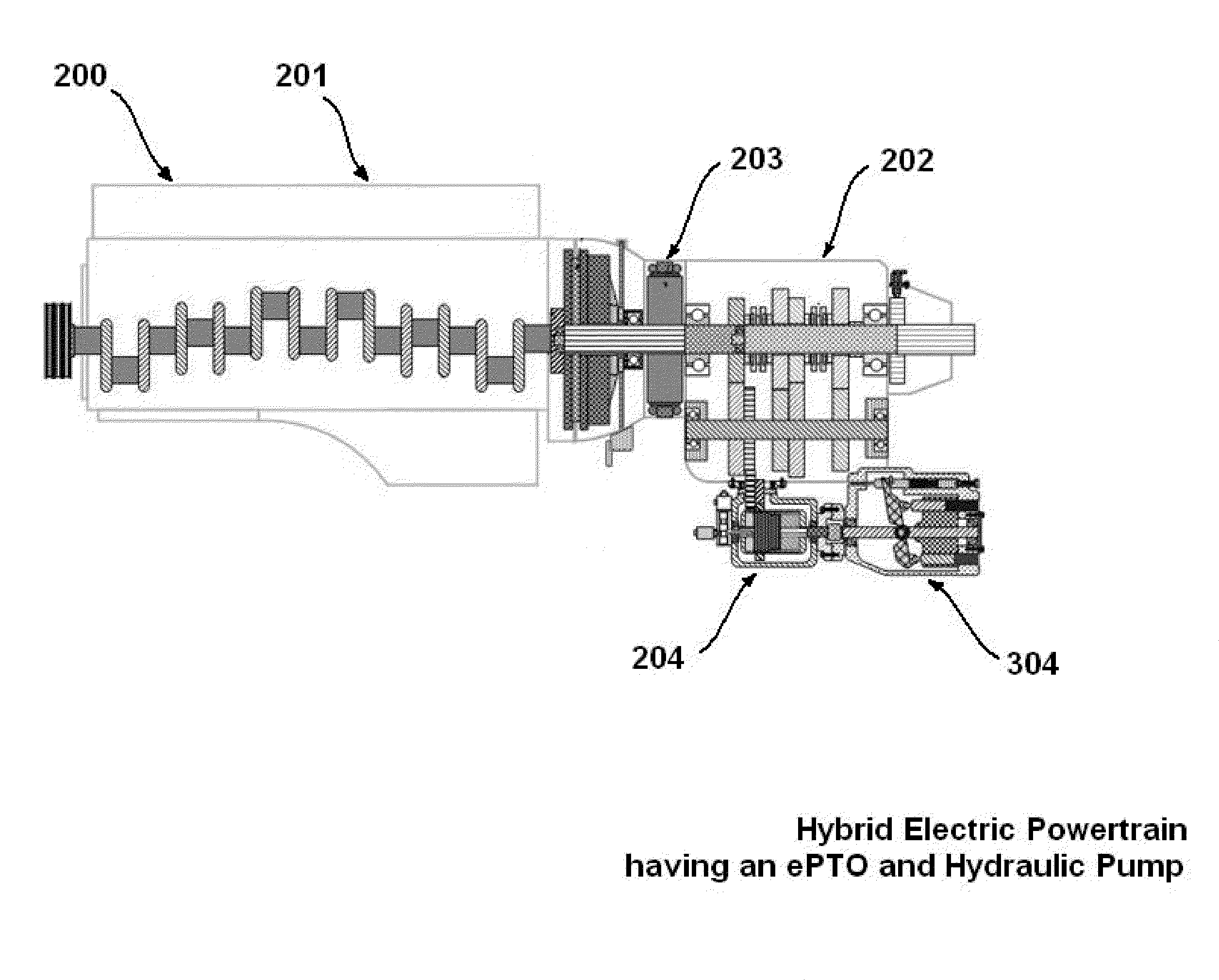
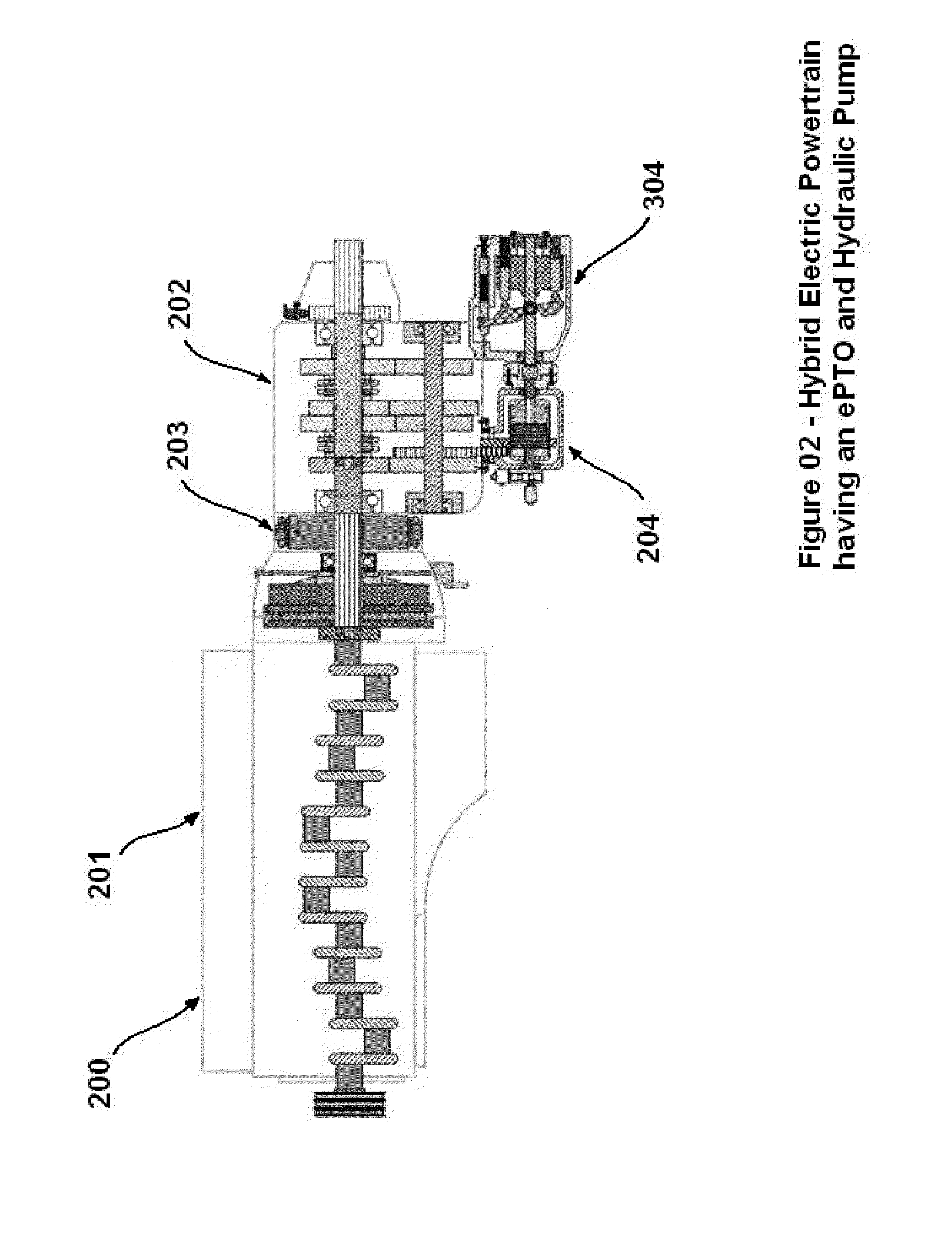
[0031]FIG. 2 shows a hybrid electric powertrain 200 having an engine 201 and a transmission 202. The transmission 202 is provided with a hybrid electric traction motor 203. The transmission 202 is further provided with a power take-off 204, which power take-off 204 may be selectively driven by the hybrid electric traction motor 203, the engine 201, or both. The power take-off 204 is connected to and drives a hydraulic pump 304.

[0032]FIG. 3 shows an embodiment of the present invention, an open center type hydraulic system 300 having provisions for use with the Hybrid Electric Vehicle Traction Motor Driven Power Take-Off Control System. The open center type hydraulic system 300 is provided with a hydraulic pump 304 and s...


PUM


Abstract

A hybrid electric work vehicle having an electric traction motor driven power take off used in conjunction with a control system that monitors the hydraulic system for pressure deltas and trend vectors, and that has learning capabilities, is provided for use with a vehicle for operation on the ground. The system is usable for both open center and closed center hydraulic systems. It is emphasized that this abstract is provided to comply with the rules requiring an abstract that will allow a searcher or other reader to quickly ascertain the subject matter of the technical disclosure. It is submitted with the understanding that it will not be used to interpret or limit the scope or meaning of the claims. 37 CFR 1.72(b).

Description

FIELD OF THE INVENTION [0001]This invention relates to a vehicle having a hybrid electric powertrain which is built as a partially complete vehicle and to which a second body manufacturer adds a body and equipment that is designed for certain specific tasks. Vehicles such as this often are provided by the initial manufacturer with a cab, a chassis having an engine, a transmission, and running gear, and certain provisions which are utilized by the second body manufacturer. One device that is often provided is a Power Take-Off (PTO) which provides mechanical power for the equipment installed by the second body manufacturer. When the vehicle has a hybrid electric powertrain, the electric traction motor which is a part of that hybrid electric powertrain may be advantageously used to provide power to the PTO when the vehicle is parked with or without the engine running. Often, the PTO provides power to a hydraulic pump, which provides hydraulic pressure to operate such devices as lifts a...

Claims


Application Information

Patent Timeline
Patent Type & Authority Applications(United States)
IPC IPC(8): B60K1/02B60W10/02
CPCB60K6/48Y10T477/26B60K25/00B60W10/30B60W20/00B60W2710/086B60Y2200/41F15B1/033F15B21/087F15B2211/20515F15B2211/3116F15B2211/6309F15B2211/6313F15B2211/6651Y02T10/6221B60K17/28B60K25/06Y02T10/62B60W20/10
Inventor BISSONTZ, JAY E.
Owner INT TRUCK INTPROP LLC
Learn More