[0017]The present invention provides a threaded joint for steel pipes which enables a pin to be easily inserted into a box even when the pin is sloping, and with which
galling does not readily take place on the stabbing flanks of the threads of the pin and the box at the time of makeup.
[0019]As proposed in above-described Patent Documents 1 and 2, if a chamfer is imparted to the stabbing flanks of the threads of both a pin and a box, although stabbing of the pin becomes easy, costs increase, and the stability of makeup of threads decreases. As a result, if compressive loads become high, a sufficient tightening force can no longer be obtained, leading to a decrease in resistance to compression. In contrast, in the present invention, because a chamfer is formed on the stabbing flanks of the threads of only one of the pin and the box, ease of stabbing of a pin can be achieved, and at the same time, adverse effects on the stability of thread makeup and resistance to compression due to forming the chamfer are minimized.
[0031]A threaded joint for steel pipes according to the present invention is preferably applied to the above-described premium joint. Namely, in a preferred embodiment, the pin and the box both have threads as well as seal surfaces provided on the
peripheral surfaces in the vicinity of the threads, and shoulder surfaces which are constituted by an end surface of one of the pin and the box and a surface of the other member which contacts the end surface. In such a threaded joint for steel pipes, the shoulder surfaces can bear a portion of a
compressive load, so the joint can maintain
high resistance to compression even when a two-step stabbing shape is employed by providing a chamfer on the stabbing flanks of the threads in the complete thread portion of one of the pin and the box according to the present invention.
[0033]When the contact surfaces of both of the pin and the box have a surface treatment
coating, the member which is given the above-described two-step stabbing shape may be either the pin or the box. As a result, damage to the surface treatment
coating at the time of
insertion of a pin can be suppressed, and good stabbing ability and good galling resistance of the threads can be obtained. In this case, if the chamfer angle β is made large, the area of the pin and the box which can undergo
sliding contact increases. As a result, damage to the surface treatment
coating is further decreased, and galling resistance of the threads is further increased.
[0034]When only one of the pin and the box has a surface treatment coating on its contact surfaces, the surface treatment coating is preferably formed on the member having threads with a two-step stabbing shape (i.e., the first tubular member). For example, when a surface treatment coating is not formed on the pin surface but formed only on the box surface, a chamfer is preferably imparted to the stabbing flank of the box thread to form a two-step stabbing shape. As a result, the point of contact between the pin threads and the box threads in the threaded portions at the time of
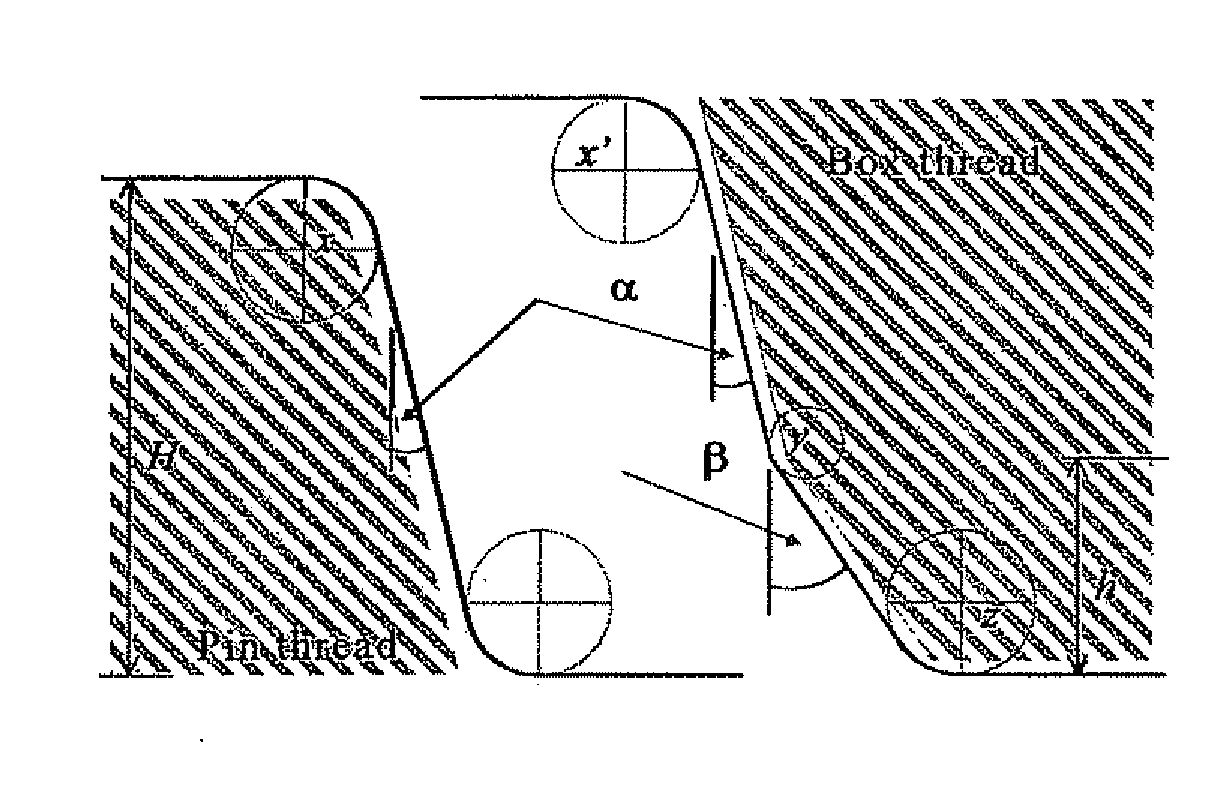
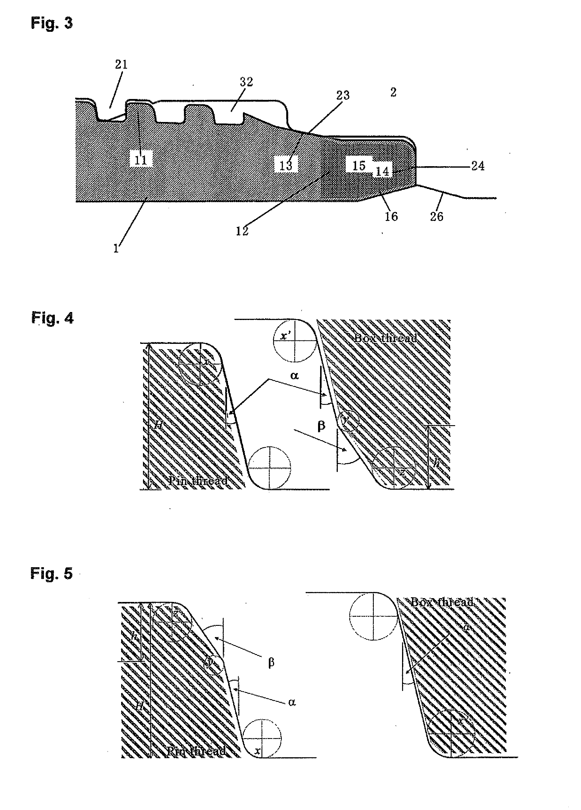
insertion of the pin into the box gradually moves from the crests of the stabbing flanks of the box threads towards the roots. Therefore, damage to the surface treatment coating decreases and good galling resistance of the threads is maintained. If the stabbing flanks of the threads of neither the pin nor the box have a chamfer, at the time of insertion of the pin, only the vicinity of the border between the crests and the stabbing flanks of the box threads always contacts the threads of the pin which is being inserted, so the surface treatment coating in this portion is severely damaged, and the galling resistance of the threads markedly decreases. Such damage is prevented in the present invention.
[0035]A threaded joint for steel pipes according to the present invention minimizes the adverse effects
on resistance to compression caused by imparting a chamfer to a stabbing flank of a thread, and it makes it easy to insert a pin into a box. As a result, a pin can be easily inserted even when the pin is sloping when being inserted or when there is a slight deviation in the insertion direction of the pin. In addition, when at least one of the pin and the box has a surface treatment coating in order to impart lubricating properties to the contact surfaces thereof, damage to the coating is suppressed. As a result, it is difficult for galling of the stabbing flank of the threads of the pin and the box to take place at the time of makeup, and the galling resistance of a threaded joint is improved.
