

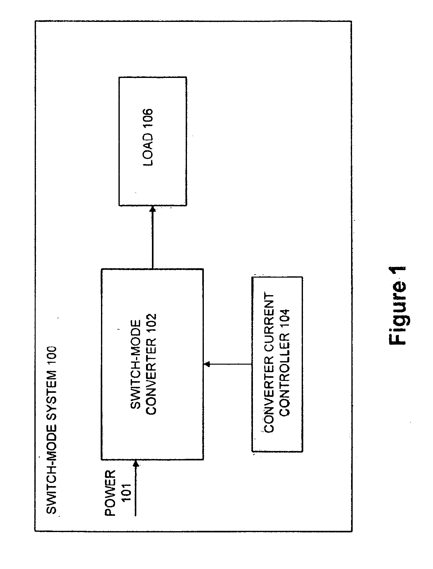
Adjustable Constant Current Source with Continuous Conduction Mode ("CCM") and Discontinuous Conduction Mode ("DCM") Operation
a constant current source and continuous conduction mode technology, applied in the field ofsignal processing, can solve problems such as the error of differential non-linearity (dnl) in the effective current digital-to-analog converter
- Summary
- Abstract
- Description
- Claims
- Application Information
AI Technical Summary
Benefits of technology
Problems solved by technology
Method used
Image

Examples
Embodiment Construction
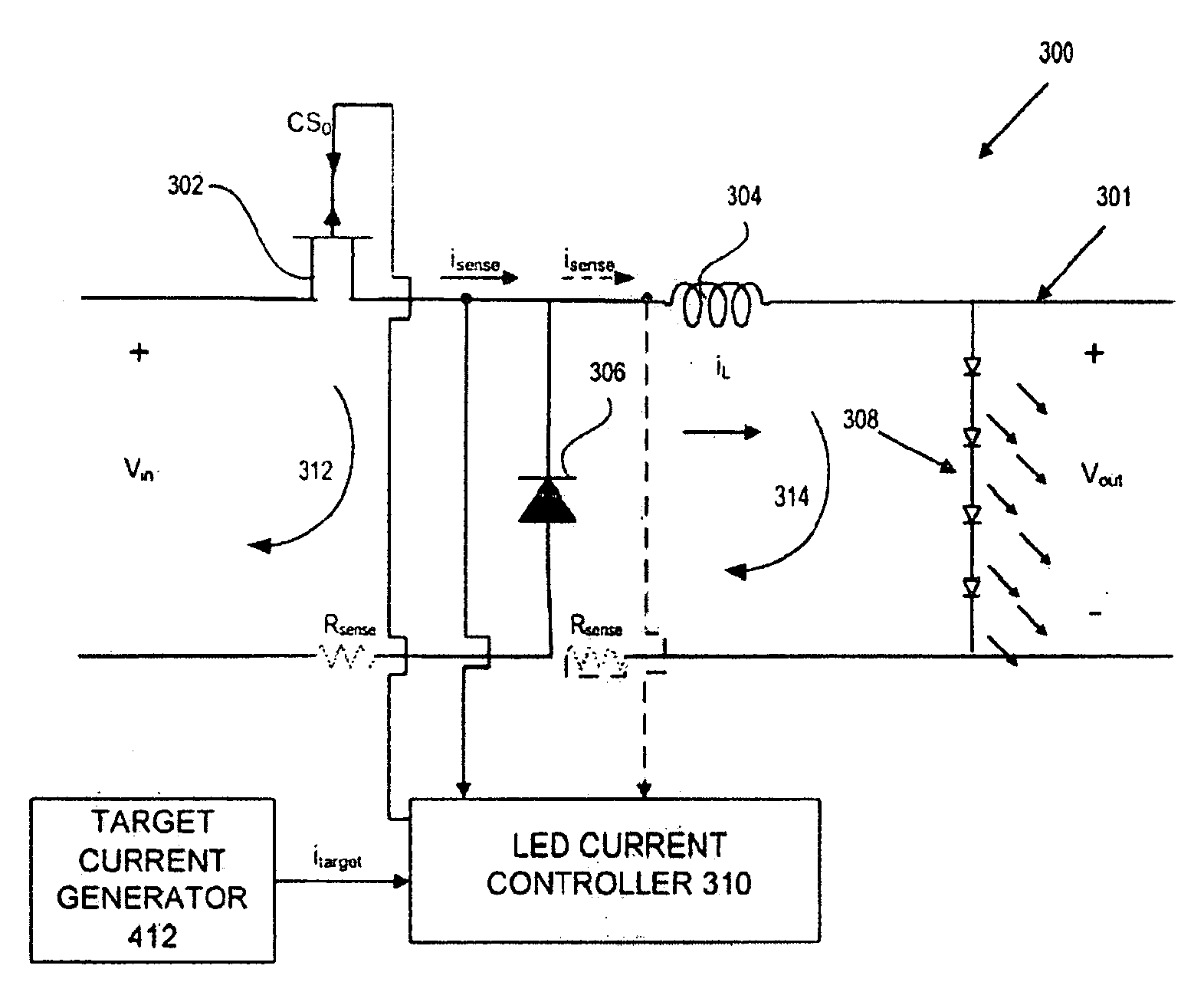
[0019]FIG. 3 depicts details of an Light Emitting Diode (“LED”) lighting system 300 having an exemplary switch-mode buck converter power stage 301 controlled by a Light Emitting Diode. (“LED”) current controller 310 for driving LEDs 308. LED lighting system 300 is an exemplary system illustrating an embodiment of the present invention, and the present invention is not in any way limited to an LED lighting system nor the use of a buck converter, LED current controller, and LEDs. The present invention can also be used for other suitable applications as well as utilize other converters / converter power stages (e.g., boost converters) or controllers.
[0020]Switch-mode buck converter power stage 301 comprises a control switch (e.g., Field Effect Transistor (“FET”)) 302 having a source and drain coupled in series with an inductor 304 as shown in FIG. 3. The source of FET 302 is coupled to a positive side of input voltage Vin. Diode 306 is coupled across the input voltage Vin in which a firs...
PUM
 Abstract
Description
Claims
Application Information