Liquid crystal display
a liquid crystal display and display technology, applied in the field of liquid crystal display technology, can solve the problems of preventing the achievement of high contrast ratio and wide viewing angle, and still has not achieved a response speed comparabl
- Summary
- Abstract
- Description
- Claims
- Application Information
AI Technical Summary
Benefits of technology
Problems solved by technology
Method used
Image
Examples
example 1
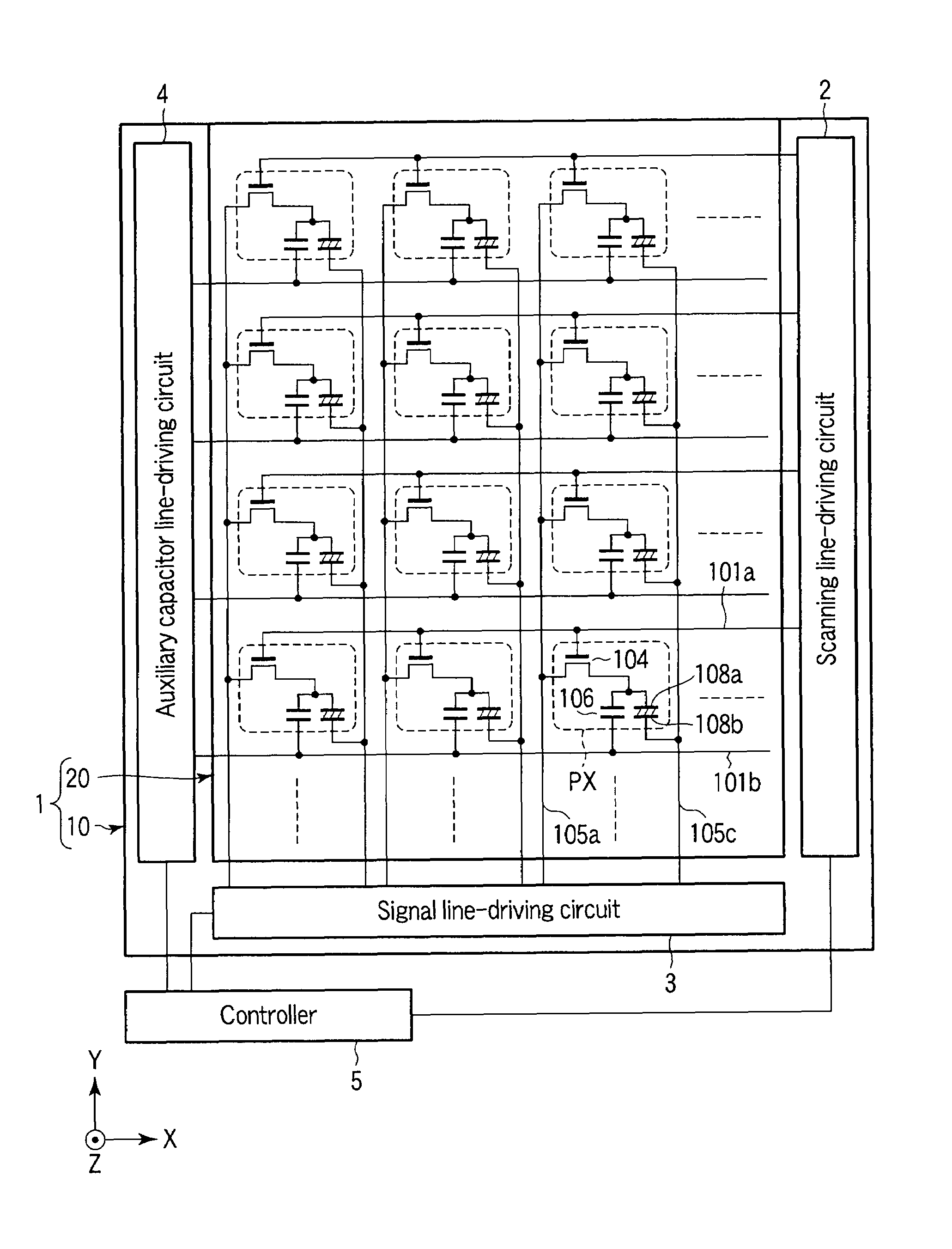
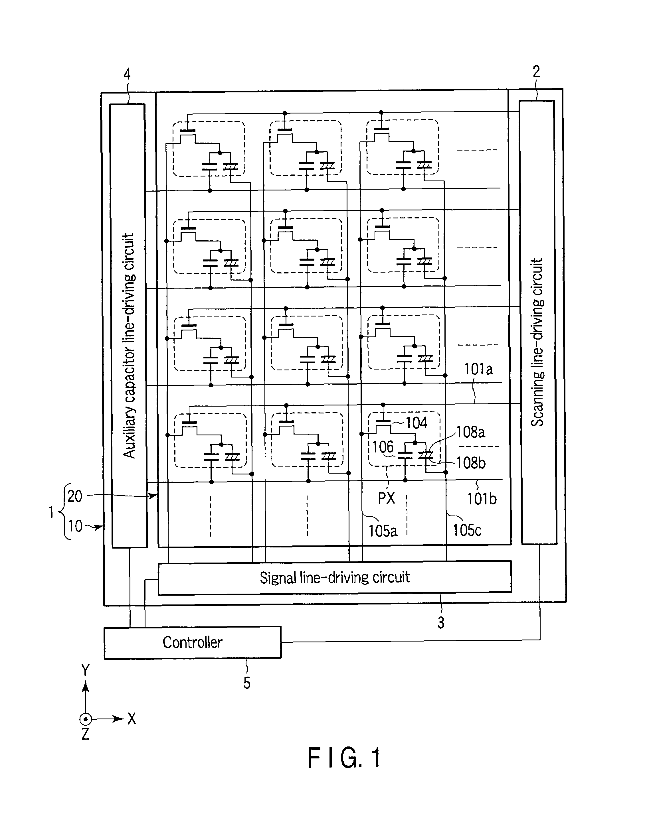
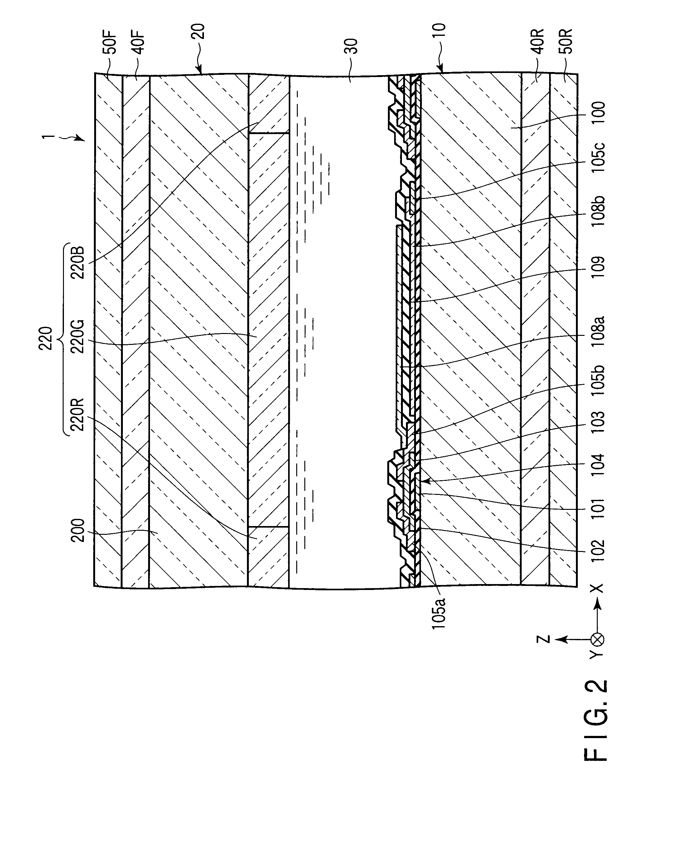
[0138]In this example, the liquid crystal display described with reference to FIGS. 1 to 3 was manufactured by the following method.
[0139]In the manufacture of the array substrate 10, the scanning lines 101a and the auxiliary capacitor lines 101b were first formed on a glass substrate 100. Chromium was used as the material of the scanning lines 101a and the auxiliary capacitor lines.
[0140]Then, the scanning lines 101a, the auxiliary capacitor lines and the glass substrate 100 were covered with the insulating film 102 made of silicon oxide. An amorphous silicon film was formed on the insulating film 102 and patterned into the semiconductor layers 103. After that, a channel protection layer (not shown) made of silicon nitride was formed on a part of each semiconductor layer 103, and ohmic layers (not shown) were formed on the semiconductor layers 103 and channel protection layers.
[0141]On the insulating film 102, the signal lines 105a, the source electrodes 105b and the power supply l...
example 2
[0152]In this example, the structure described with reference to FIG. 7 was employed in the counter electrodes 108b instead of employing the structure described with reference to FIGS. 1 to 3 in the counter electrodes 108b. A liquid crystal display was manufactured by the same method as that described in Example 1 except for the above.
[0153]Then, the display was driven by the same method as that described in Example 1 and its performance was evaluated. As a result, a response speed of 1 millisecond and a contrast ratio of 1000:1 were achieved.
example 3
[0154]In this example, employed was a design in which the circular polarizer including the quarter-wave plate 40F and the linearly polarizing plate 50F was a left-handed circular polarizer and the circular polarizer including the quarter-wave plate 40R and the linearly polarizing plate 50R was a right-handed circular polarizer. To be more specific, the directions of the transmission axes of the linearly polarizing plates 50F and 50R were rotated by 90° with respect to the directions of the transmission axes of the linearly polarizing plates 50F and 50R in the liquid crystal display manufactured in Example 1. A liquid crystal display was manufactured by the same method as that described in Example 1 except for the above.
[0155]Then, the display was driven by the same method as that described in Example 1 and its performance was evaluated. As a result, its contrast ratio was 100:1. In addition, the screen was seen bluish when displaying a black image.
PUM
 Abstract
Description
Claims
Application Information
 - R&D
- Intellectual Property
- Life Sciences
- Materials
- Tech Scout
- Unparalleled Data Quality
- Higher Quality Content
- 60% Fewer Hallucinations
Browse by: Latest US Patents, China's latest patents, Technical Efficacy Thesaurus, Application Domain, Technology Topic, Popular Technical Reports.
© 2025 PatSnap. All rights reserved.Legal|Privacy policy|Modern Slavery Act Transparency Statement|Sitemap|About US| Contact US: help@patsnap.com


