Cutting Insert

a technology of inserts and cutting holes, which is applied in the direction of metal-working equipment, metal-working equipment, milling equipment, etc., can solve the problems of increased time needed for tool production, increased tool production time, and increased load on the clamping arm

Active Publication Date: 2010-04-01
ISCAR LTD
View PDF6 Cites 67 Cited by
  • Summary
  • Abstract
  • Description
  • Claims
  • Application Information

AI Technical Summary

Benefits of technology

[0014]It is a further object of the present invention to provide a cutting insert th

Problems solved by technology

The clamping arm, an important element for rigid clamping and, hence, stable cutting, comprises a number of parts, and thus can cause a certain amount of inconvenience for an operator due to the necessity to use two different wrenches for insert indexing or replacing, namely, one for the clamping screw and the other for the clamping arm.
Another disadvantage of using a clamping arm is the increased time necessary for the tool production, since there are more machining and assembling operations.
Furthermore, the clamping arm is an obstacle for free

Method used


Image

  • Cutting Insert
  • Cutting Insert
  • Cutting Insert

Examples


Embodiment Construction

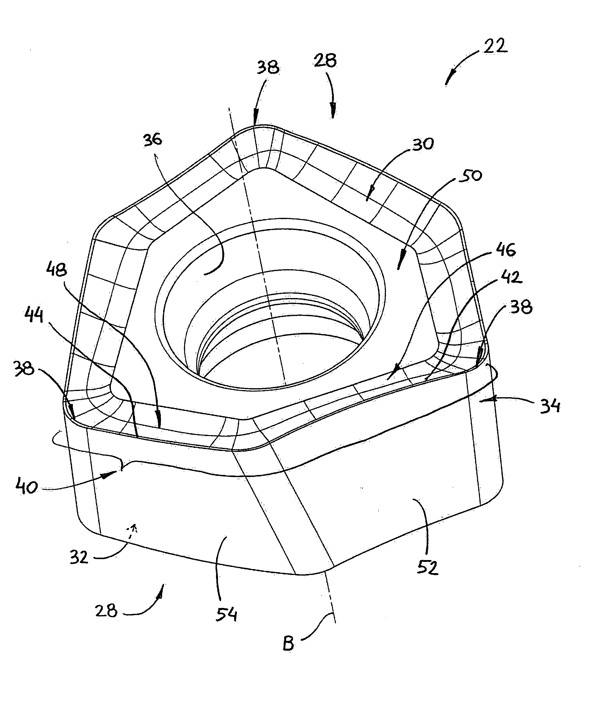
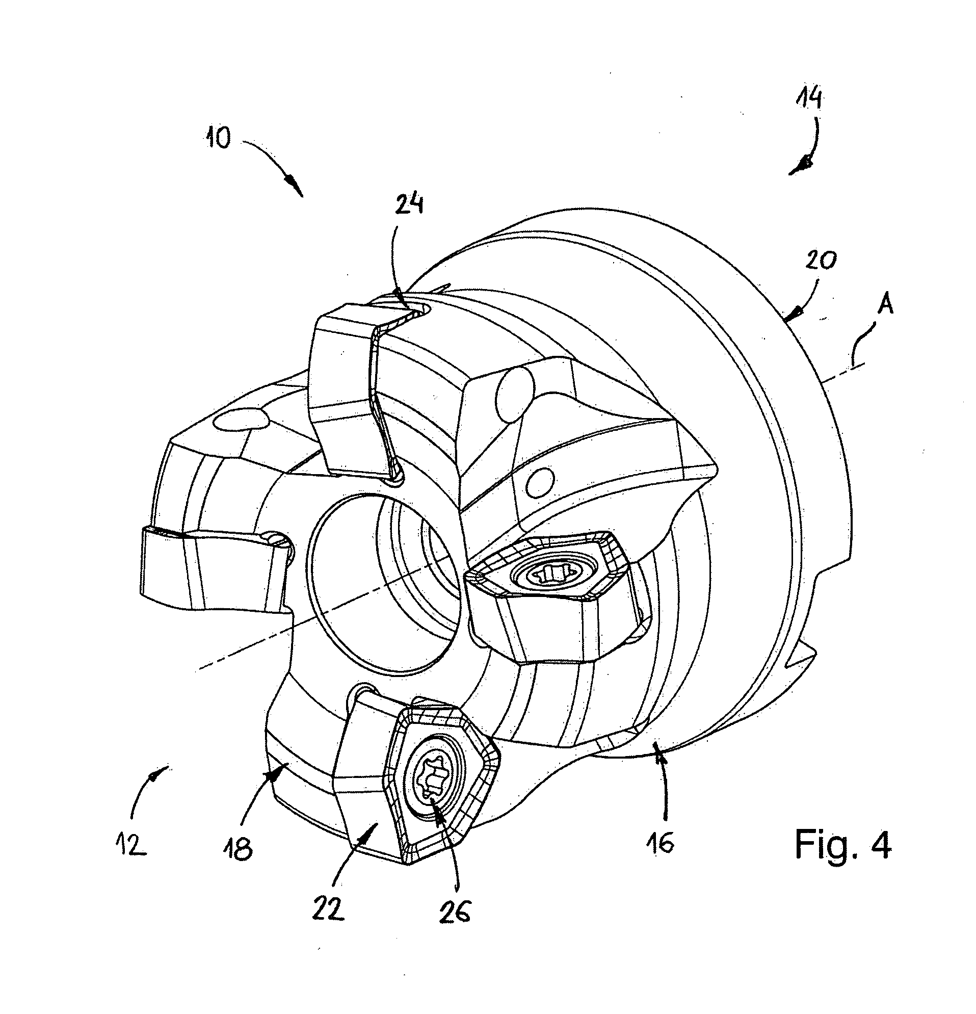
[0063]Attention is first drawn to FIG. 4 showing a cutting tool 10 in accordance with the present invention. The cutting tool 10 has a longitudinal axis of rotation A defining a front end 12 and a rear end 14. The cutting tool 10 comprises a tool body 16 having a front end 18 and a rear end 20. The tool body 16 has a plurality of cutting inserts 22 mounted therein. Each of the cutting inserts 22 is seated within an insert pocket 24 and retained by a clamping bolt 26.

[0064]Attention is now drawn to FIGS. 5 to 9. The cutting insert 18 has a generally trigonal shape and comprises two opposing identical end surfaces 28, namely, an upper surface 30 and a lower surface 32. A peripheral surface 34 extends between the two end surfaces 28. A through bore 36 having a bore axis B extends between the two end surfaces 28. Since the two end surfaces 28 are identical, only one of them will be described.

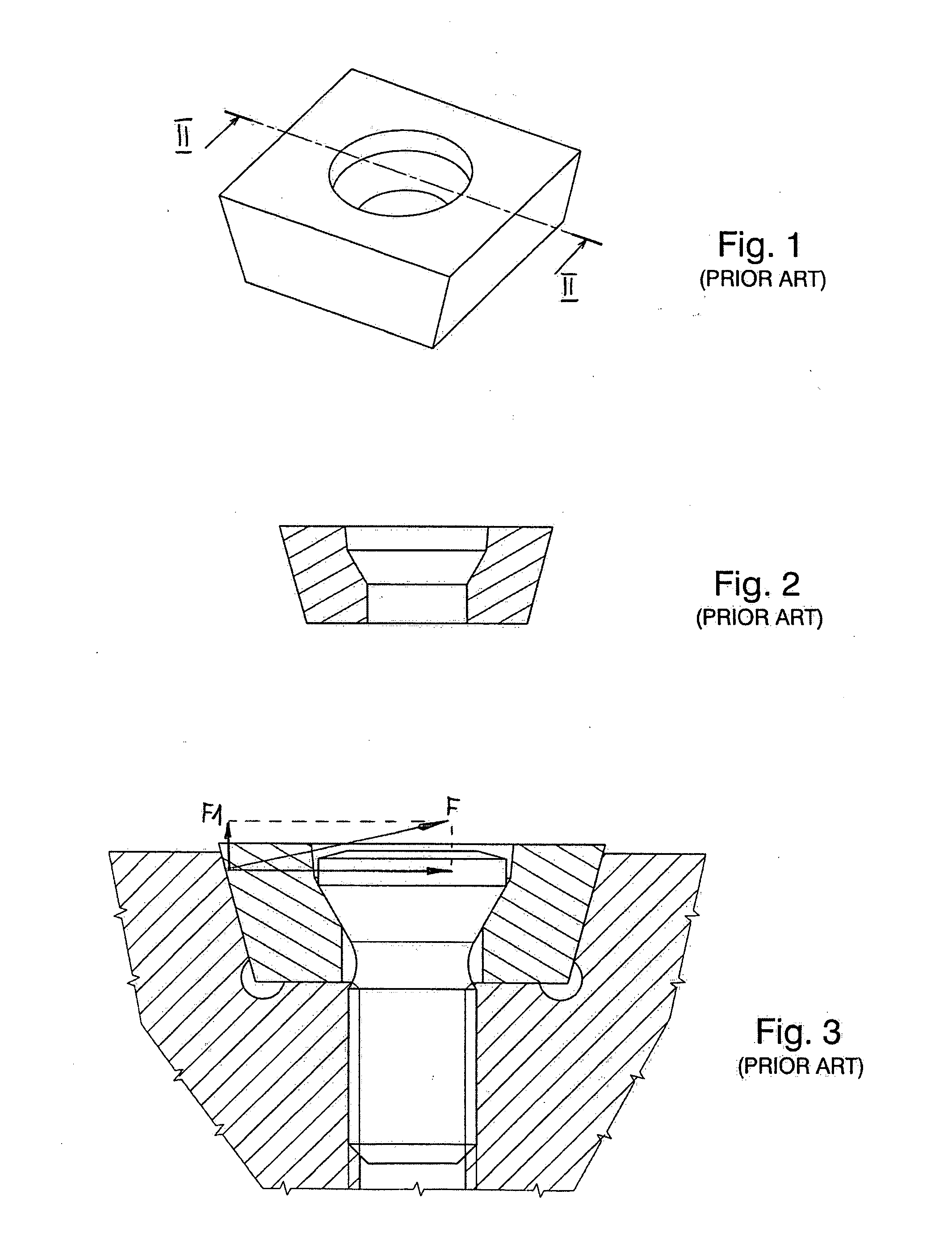
[0065]The intersection between the upper surface 30 and the peripheral surface 34 forms cutting ...


PUM

PropertyMeasurementUnit
Angleaaaaaaaaaa
Shapeaaaaaaaaaa

Abstract

A cutting insert has a trigonal shape. The cutting insert has a peripheral surface that extends between two opposing identical end surfaces. A median plane (M) bisects the cutting insert between the end surfaces. A through bore extends between the end surfaces. A cutting edge, formed at the intersection of each end surface with the peripheral surface, is divided into three identical cutting sections. Each cutting section is located between two vertexes of the trigonal shape. Each cutting section has a convex primary cutting edge and a concave secondary cutting edge that merge together. An insert tangential abutment surface is located between the cutting edge and the through bore. A primary relief surface forms an insert internal obtuse angle with a first reference plane (P1). A secondary relief surface forms an insert internal acute angle with a second reference plane (P2).

Description

FIELD OF THE INVENTION[0001]The present invention relates to cutting inserts for high speed milling combined with ramp down operations.BACKGROUND OF THE INVENTION[0002]A milling technique known as high feed milling or HFM is characterized by a low engagement into a workpiece, in axial direction relative to a tool axis, and a high feed rate. The high speed milling machining method is widespread in industry. There are many cutting geometries which allow realizing this technique. Some geometries can be observed on solid tools and replaceable solid heads and others have been realized with different cutters having indexable cutting inserts mounted therein.[0003]Ramping or a ramp down milling is known as a milling process with a lateral feed combining an axial feed. Due to the ability to achieve high metal removal rate in rough milling with relatively light machine tools the mentioned technique is very popular in the die and mold industry. Machining cavities and pockets is a typical appli...

Claims


Application Information

Patent Timeline
IPC IPC(8): B23C5/20B23C5/22
CPCB23C5/2213Y10T407/22B23C2200/0444B23C2200/085B23C2200/123B23C2200/203B23C2200/206B23C2210/168B23C2210/445B23C2220/44Y10T407/23Y10T407/192Y10T407/1924Y10T407/235Y10T407/1936B23C2200/0411B23C2200/284B23C2200/283B23C5/06B23C2210/165B23C2200/045
Inventor SATRAN, AMIRMEN, YURIPASSOV, ALEXANDER
Owner ISCAR LTD
Why Eureka
Try Eureka