System and method for temperature control of multi-battery systems

a multi-battery and temperature control technology, applied in the direction of battery/fuel cell control arrangement, electric devices, electrochemical generators, etc., can solve the problems of low ambient temperature, limited power level allowed to recharge batteries, further temperature variations, etc., and achieve the effect of reducing the operating temperature of the second battery

Active Publication Date: 2010-04-15
GENERAL ELECTRIC CO
View PDF21 Cites 126 Cited by
  • Summary
  • Abstract
  • Description
  • Claims
  • Application Information

AI Technical Summary

Benefits of technology

[0007]Aspects of the invention provide a system including a first battery having a first desired operating temperature range between a first lower threshold temperature and a first upper threshold temperature and a second battery having a second desired operating temperature range between a second lower threshold temperature and a second upper threshold temperature. The second upper threshold temperature is less than the first lower threshold temperature. The system further includes a temperature control system coupled to the first and second batteries and configured to convey heat energy from the first battery to the second battery when the temperature of the second battery is less than the second lower threshold temperature to increase the temperature of the second battery toward the second desired operating temperature range and to convey heat energy away from the second battery

Problems solved by technology

Further, “under-the-hood” systems of such vehicles, such as an internal combustion engine (ICE) and/or other adjacent propulsion and auxiliary components, often cause further temperature variations.
Similarly, the power level allowed to recharge the batteries, either by the utility grid to a BEV or PHEV or by regenerative braking, is also often limited at low ambient temperatures.
Suc

Method used


Image

  • System and method for temperature control of multi-battery systems
  • System and method for temperature control of multi-battery systems
  • System and method for temperature control of multi-battery systems

Examples


Embodiment Construction

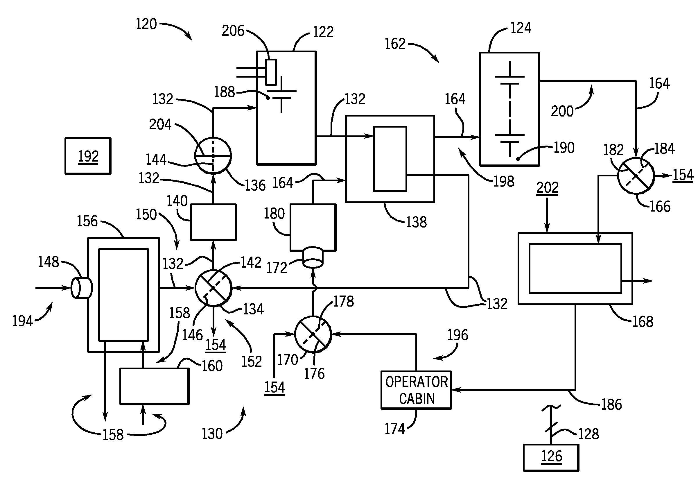
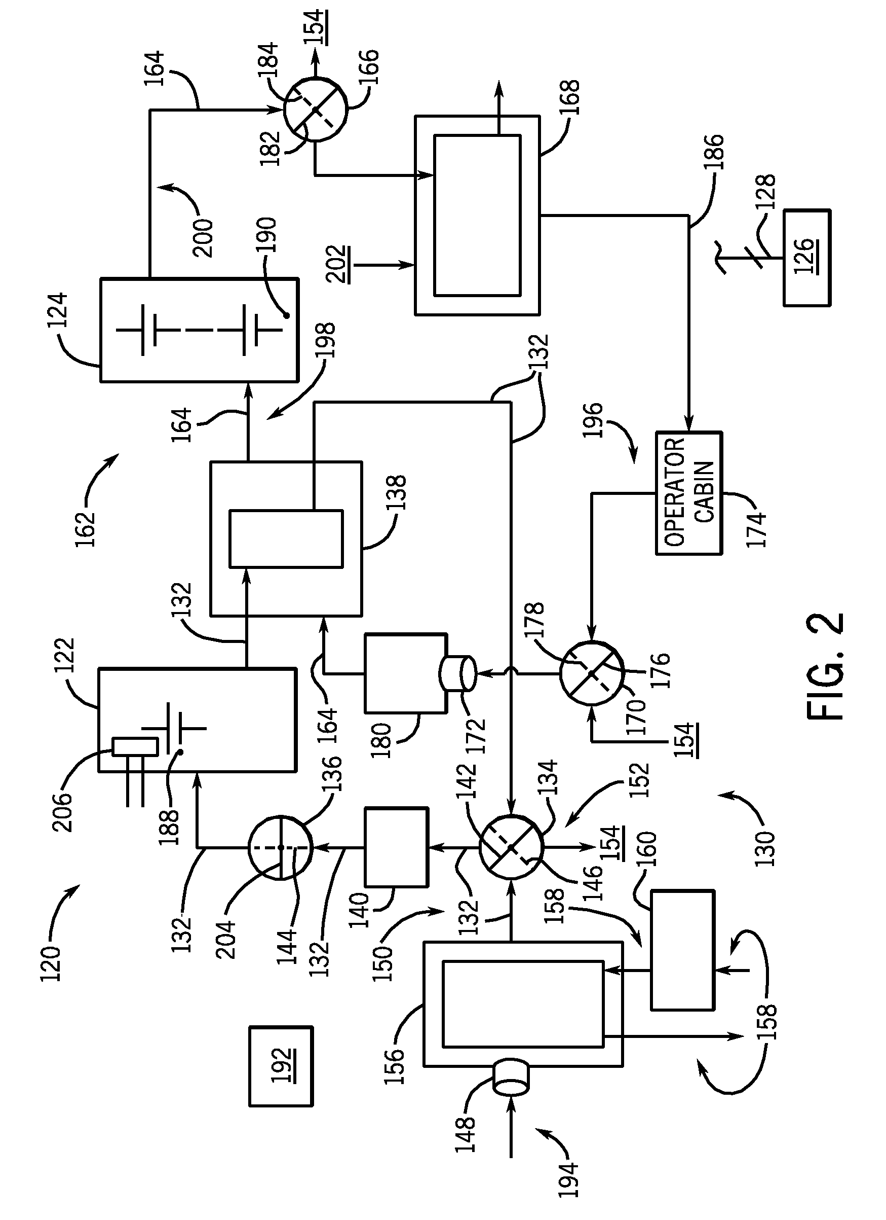
[0017]The invention includes embodiments that relate to battery temperature control systems for systems and apparatuses that use multiple batteries. Embodiments of the invention may be implemented in a wide variety of systems that rely on multiple batteries. For example, embodiments of the inventions may be implemented in vehicles such as hybrid-electric vehicles, locomotives, generators, and other systems that use more than one battery.

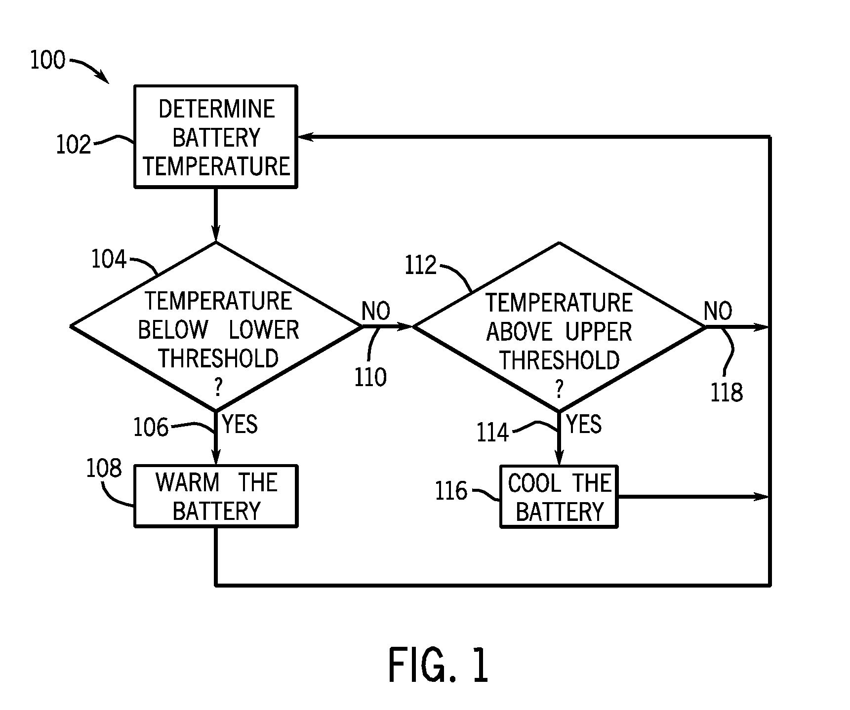
[0018]Referring to FIG. 1, a flowchart depicting an operational overview of battery temperature maintenance in a multiple battery temperature control system according to an embodiment is shown. Often, batteries of a system operate optimally if the temperatures of such batteries are within a particular temperature range. In addition, the particular optimal temperature ranges may be different for differing batteries being used in the system. Technique 100 begins at BLOCK 102, where the temperature of a battery is determined. At decision BLOCK 104, the ...


PUM


Abstract

An system includes a first battery having a first desired operating temperature range between a first lower threshold temperature and a first upper threshold temperature and a second battery having a second desired operating temperature range between a second lower threshold temperature and a second upper threshold temperature. The system further includes a temperature control system coupled to the first and second batteries and configured to convey heat energy from the first battery to the second battery when the temperature of the second battery is less than the second lower threshold temperature to increase the temperature of the second battery toward the second desired operating temperature range and to convey heat energy away from the second battery when the temperature of the second battery is greater than the second upper threshold temperature to decrease the temperature of the second battery toward the second desired operating temperature range.

Description

BACKGROUND[0001]The invention relates generally to multi-battery systems and, more particularly, to a temperature control system for multiple batteries.[0002]A wide variety of devices, apparatuses, or systems use multiple batteries to power various aspects and / or components thereof. Often, such batteries operate optimally within a defined temperature range. That is, batteries of such devices operate optimally when the temperatures of such batteries are kept within a determined or defined temperature operating range. Further, two or more batteries of such devices may have preferred temperature operating ranges that differ from one another. To maintain operating temperatures of batteries, energy is often consumed for heating and cooling purposes.[0003]Multi-battery systems in vehicles such as a battery electric vehicle (BEV), a hybrid-electric vehicle (HEV), or a plug-in hybrid electric vehicle (PHEV) generally include an energy storage system capable of operation over a wide range of...

Claims


Application Information

Patent Timeline
IPC IPC(8): B60H1/22
CPCB60L3/0046Y02T90/34B60L11/1855B60L11/1875H01M10/486H01M10/5004H01M10/5006H01M10/5016H01M10/5022H01M10/5067H01M10/5083H01M10/5095Y02T10/7005Y02T10/7011Y02T10/705B60L3/0053H01M10/625H01M10/615H01M10/633H01M10/663H01M10/6563H01M10/6571H01M10/613B60L58/19B60L58/27B60L58/26B60L58/34B60L58/33Y02T10/70Y02T90/40Y02E60/10
Inventor KING, ROBERT DEANHOFSTETTER, LORNE WYATT
Owner GENERAL ELECTRIC CO
Why Eureka
Try Eureka