
Method and apparatus for pulsed power generation

a technology of pulsed power and generators, applied in the direction of electric pulse generators, thermonuclear fusion reactors, gas-filled discharge tubes, etc., can solve the problem of relatively low energy storage density of typical high-voltage capacitors, and achieve the effect of reducing or eliminating, and sufficient reliability

Active Publication Date: 2010-04-15
AUCHTERLONIE RICHARD CARL
View PDF7 Cites 25 Cited by
  • Summary
  • Abstract
  • Description
  • Claims
  • Application Information

AI Technical Summary

Benefits of technology

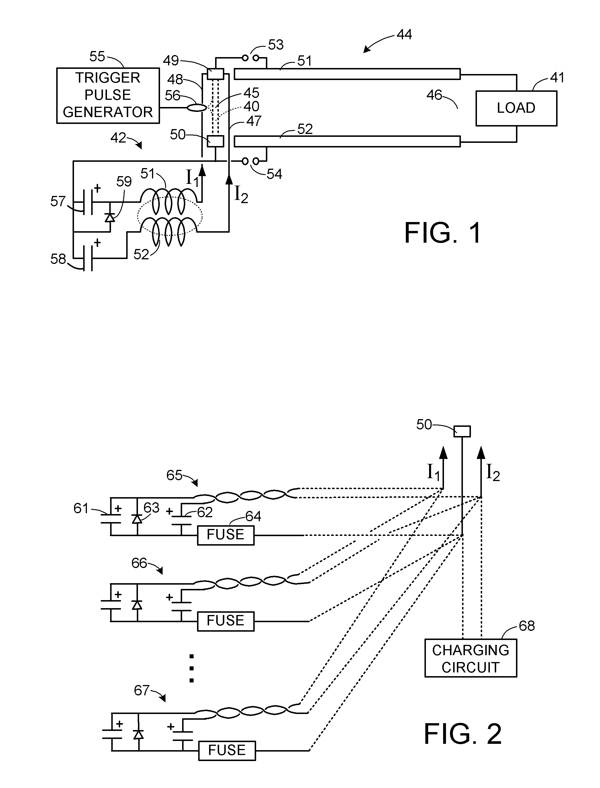
[0008]A first aspect of the present invention is directed to reducing or eliminating a need for command triggered opening of plasma switches in a pulsed power system employing inductive energy storage. In particular it is desired for an array of plasma switches sharing a vacuum chamber to perform most or all of the active switching functions of the pulsed power system. This is desired to enable repetitive operation with sufficient reliability for commercial applications such as nuclear fusion power generation. This is done by one or more of the following techniques: (1) wiring the current sources for first and second currents for respective plasma opening switches in series with all of the plasma opening switches in an array so that that the plasma opening switches close in synchronism, and the opening time of each plasma opening switch is independently adjustable; (2) a data collection system for recording the opening time of each plasma opening switch in the array; (3) a feedback control method of adjusting the plasma switch opening times for a next shot in response to the recorded plasma switch opening times of one or more previous shots; (4) command triggered opening of plasma opening switches in the array in real time for a shot as needed in response to asymmetry of opening times of the plasma opening switches in the array during the shot; or (5) the use of a capacitor pulsed power supply or a magnetic flux compression generator that generates a power pulse at a specified time and produces a difference signal at the beginning of a terminal portion of the power pulse in order to switch the plasma opening switch from the closed state to the open state.

Problems solved by technology

Unfortunately, the energy storage density of a typical high-voltage capacitor is relatively low, especially if the capacitor is rated for repetitive operation.
Due to the limitations of high-voltage capacitor banks, there has been considerable effort toward developing pulsed power generators using stored inductive energy.

Method used


Image

  • Method and apparatus for pulsed power generation
  • Method and apparatus for pulsed power generation
  • Method and apparatus for pulsed power generation

Examples


Embodiment Construction

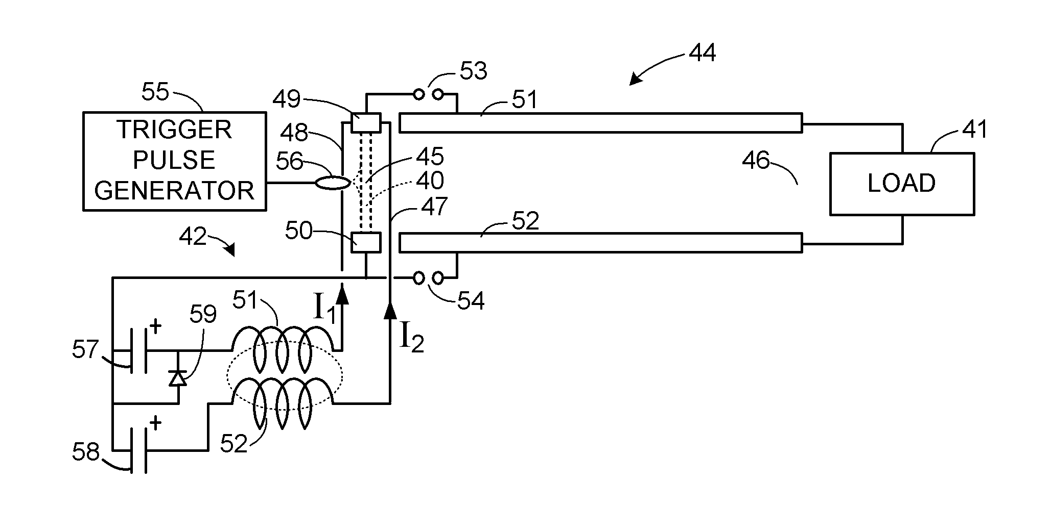
[0043]With reference to FIG. 1, there is shown pulsed power system for supplying pulsed power to a load 41. The pulsed power system includes an inductive energy storage circuit 42 including electrolytic capacitors 57 and 58 and a plasma opening switch 44. The plasma opening switch 44 has a transmission line including spaced conductors 51, 52 coupling the current source 43 to the load 41 for supplying current to the load. The transmission line extends away from a first region 45 toward a second region 46 near the load 41. The plasma opening switch has a closed state, as shown in FIG. 1. In the closed state, a plasma discharge 40 (represented by a pair of dashed lines) is located in the first region 45. The plasma opening switch changes from the closed state to an open state when the plasma discharge 40 is driven by magnetic force from the first region 45 to toward the second region 46.

[0044]As further shown in FIG. 1, the pulsed power system includes electrical conductors 47 and 48 a...


PUM


Abstract

Respective pulsed power supplies for plasma opening switches each produce a first current and a second current during a power pulse and a difference between the first current and the second current during a terminal portion of the power pulse. The pulsed power supplies are initiated or adjusted in response to measured opening times of the plasma opening switches in order to minimize or eliminate a need for command triggered opening of the plasma opening switches. Command triggered opening may occur in real time for a shot as needed in response to asymmetry of opening times of the plasma opening switches in the array during the shot.

Description

RELATED APPLICATIONS[0001]The present application claims the benefit of U.S. Provisional Application Ser. 60 / 555,937 filed Mar. 24, 2004, incorporated herein by reference. The present application is a continuation-in-part of International Application PCT / US / 2005 / 009723 filed 23 Mar. 2005 and published on 13 Oct. 2005 as WO 2005 / 094502 and entered in the U.S. national phase as U.S. application Ser. No. 10 / 599,251 filed 22 Sep. 2006, incorporated herein by reference.FIELD OF THE INVENTION[0002]The present invention relates to pulsed power generators and pulsed power systems using inductive energy storage and opening switches.BACKGROUND OF THE INVENTION[0003]Pulsed power has a number of military, industrial, and scientific applications, such as the production of X-rays and nuclear fusion. For most applications, a high-voltage capacitor bank is discharged for pulsed power production. Unfortunately, the energy storage density of a typical high-voltage capacitor is relatively low, especia...

Claims


Application Information

Patent Timeline
Patent Type & Authority Applications(United States)
IPC IPC(8): H03K3/00H01H47/00
CPCH01J17/36H05H1/46H02J17/00H02J4/00H02J50/10H02J50/402
Inventor AUCHTERLONIE, RICHARD CARL
Owner AUCHTERLONIE RICHARD CARL
Learn More