Actuator system

a technology of actuator and actuator, which is applied in the field of actuator systems, can solve the problems of large energy consumption, low power requirement of robots, and decrease in payload capacity, and achieve the effects of high power consumption, high power on demand, and convenient robots capable of carrying heavier payloads

Active Publication Date: 2010-04-15
BOSTON DYNAMICS INC
View PDF13 Cites 54 Cited by
  • Summary
  • Abstract
  • Description
  • Claims
  • Application Information

AI Technical Summary

Benefits of technology

[0011]It is a further object of this invention to provide such a system which, in one example, does not require a larger hydraulic system power plant or consume high power when delivering low force at high flow.
[0012]It is a further object of this invention to provide such a system which facilitates robots capable of carrying heavier payloads.
[0013]The subject invention results from the realization, in part, that an actuator system in one example for a robotic or bionic linkage which enables high power on demand while enabling low power operations when desired includes a hydraulic circuit which switches in an additional piston-cylinder assembly as needed to increase the effective area of the actuator. The additional actuators enable a reduction in the average power required reducing heat production, allowing a longer operational time, less wear, the use of lighter components, and the like. These actuators allow a reduction in the flow required when high forces are not needed by reducing the area of the piston. For a given stroke, the flow and the average power are reduced.

Problems solved by technology

The combined result is a high power requirement.
This results in large energy consumption when there is high flow, even when the force is low.
Increasing the size and capability of the power plant, however, means the payload capacity of the robot decreases.
Similar problems exist with other robots, powered exoskeletons, and prosthetic arms and legs.
Known hydraulic systems for industrial forklifts and the like are not suitable for use with robotics or bionics where a controller is used to electronically actuate the various hydraulic system valves based on a desired behavior.

Method used


Image

  • Actuator system
  • Actuator system
  • Actuator system

Examples


Embodiment Construction

[0026]Aside from the preferred embodiment or embodiments disclosed below, this invention is capable of other embodiments and of being practiced or being carried out in various ways. Thus, it is to be understood that the invention is not limited in its application to the details of construction and the arrangements of components set forth in the following description or illustrated in the drawings. If only one embodiment is described herein, the claims hereof are not to be limited to that embodiment. Moreover, the claims hereof are not to be read restrictively unless there is clear and convincing evidence manifesting a certain exclusion, restriction, or disclaimer.

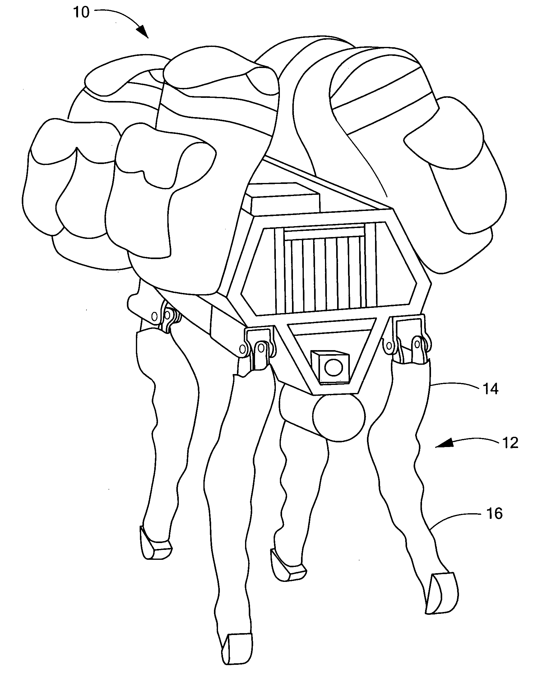
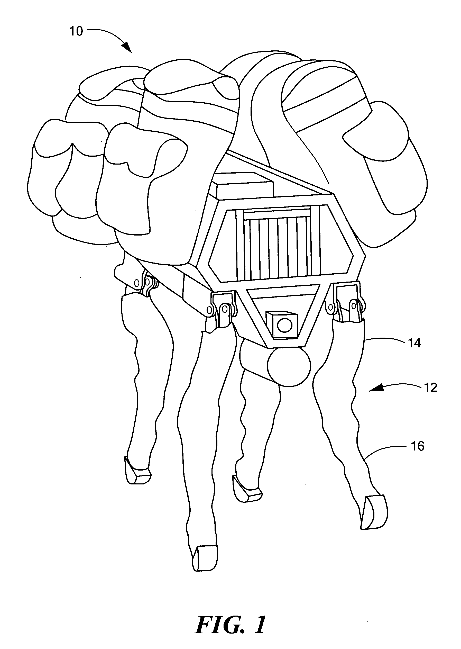
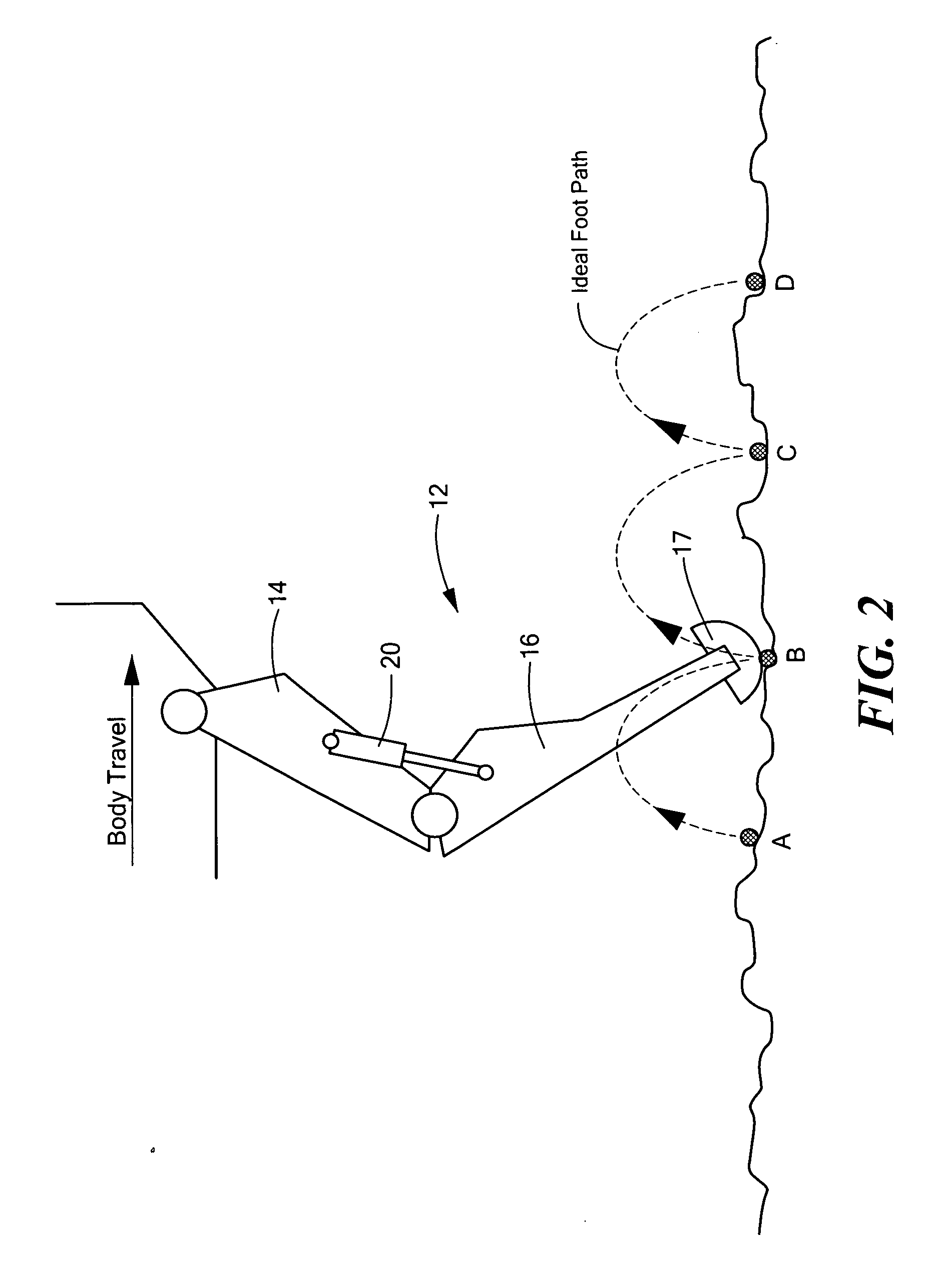
[0027]The subject invention can be employed with a variety of different robotic and bionic systems, but as one example, FIG. 1 shows a legged robot 10 called “BigDog” under development by the applicant hereof (Boston Dynamics, Inc., Waltham, Mass.). Foreleg 12 includes thigh member 14 and shin member 16. FIG. 2 shows, in a ...


PUM


Abstract

An actuator subsystem preferably for a robot or bionic linkage. A joint between two robotic or bionic members includes at least first and second actuators such as piston-cylinder assemblies connected between the members. A hydraulic circuit includes a sensor subsystem for sensing the magnitude of the load on the piston-cylinder assemblies and / or members. A fluid supply system includes an actuatable control valve operable to supply fluid to one or both piston-cylinder assemblies. A control circuit is responsive to the sensor and is configured to electronically control the fluid subsystem to supply fluid to the first piston-cylinder assembly when the sensor subsystem senses a load below a predetermined magnitude and to supply fluid to both piston-cylinder assemblies when the sensor subsystem senses a load above the predetermined magnitude.

Description

FIELD OF THE INVENTION[0001]This subject invention relates to robotics, bionics, and hydraulic system therefor.BACKGROUND OF THE INVENTION[0002]In robotics and bionics (including powered exoskeletons and prostheses), it is common to drive various articulating and jointed members using hydraulic piston-cylinder assemblies.[0003]For example, the applicant's “BigDog” four-legged robot includes numerous hydraulic piston-cylinder assemblies associated with the legs of the robot. These assemblies and the associated hydraulic circuit enable the quadruped robot to walk, run, climb, traverse rough terrain, and carry heavy loads. A gasoline engine drives the hydraulic actuation system. The robot's legs articulate like an animal's legs and have compliant elements that absorb shock and recycle energy from one step to the next. The “BigDog” robot is the size of a large dog or a small mule, measuring 1 meter long, 0.7 meters tall, and weighing 75 kilograms. The robot has an on-board computer that...

Claims


Application Information

Patent Timeline
Patent Type & Authority Applications(United States)
IPC IPC(8): B25J5/00F01L15/00
CPCB25J9/144F15B11/20F15B2211/781F15B2211/7107F15B15/1404
Inventor SAUNDERS, AARONRAIBERT, MARC
Owner BOSTON DYNAMICS INC
Why Eureka
Try Eureka