Real image forming eye examination lens utilizing two reflecting surfaces with non-mirrored central viewing area

Inactive Publication Date: 2010-04-15
VOLK DONALD A
View PDF2 Cites 39 Cited by
  • Summary
  • Abstract
  • Description
  • Claims
  • Application Information

AI Technical Summary

Benefits of technology

[0011]Based on the foregoing there is found to be a need to provide a real image forming gonioscopy lens that avoids the problems associated with the prior art lenses and which in particular provides an inverted real image of the structures of the eye, has excellent optical attributes and good magnification properties, is easily positioned and manipulated within the orbital area of the examined eye, provides visualization through the center of the lens that

Problems solved by technology

Furthermore the field of view obtainable through each mirror is very small.
Although the '779 patent presents a theoretically plausible real image forming gonioscopy lens design, the complexity required of the majority of embodiments in order to provide a correctly oriented real image and to redirect highly angulated light rays proceeding from the intermediate image to the final correctly oriented image results in aberrations that precludes its use in diagnostic or treatment applications.
Other less complex embodiments of the '779 patent employing fewer lens elements display either chromatic aberration, severe field curvature, low magnification and/or glaring reflections from

Method used


Image

  • Real image forming eye examination lens utilizing two reflecting surfaces with non-mirrored central viewing area
  • Real image forming eye examination lens utilizing two reflecting surfaces with non-mirrored central viewing area
  • Real image forming eye examination lens utilizing two reflecting surfaces with non-mirrored central viewing area

Examples


first embodiment

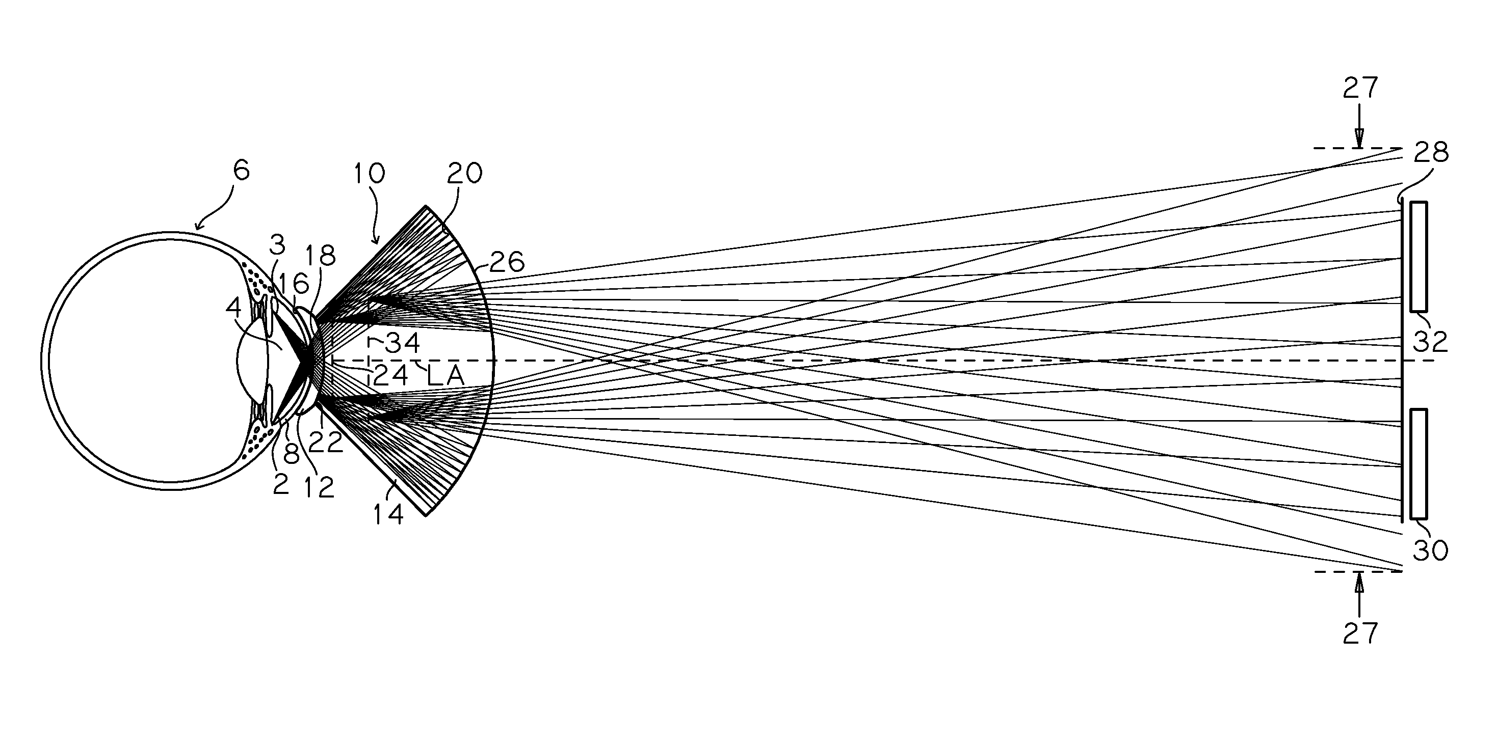
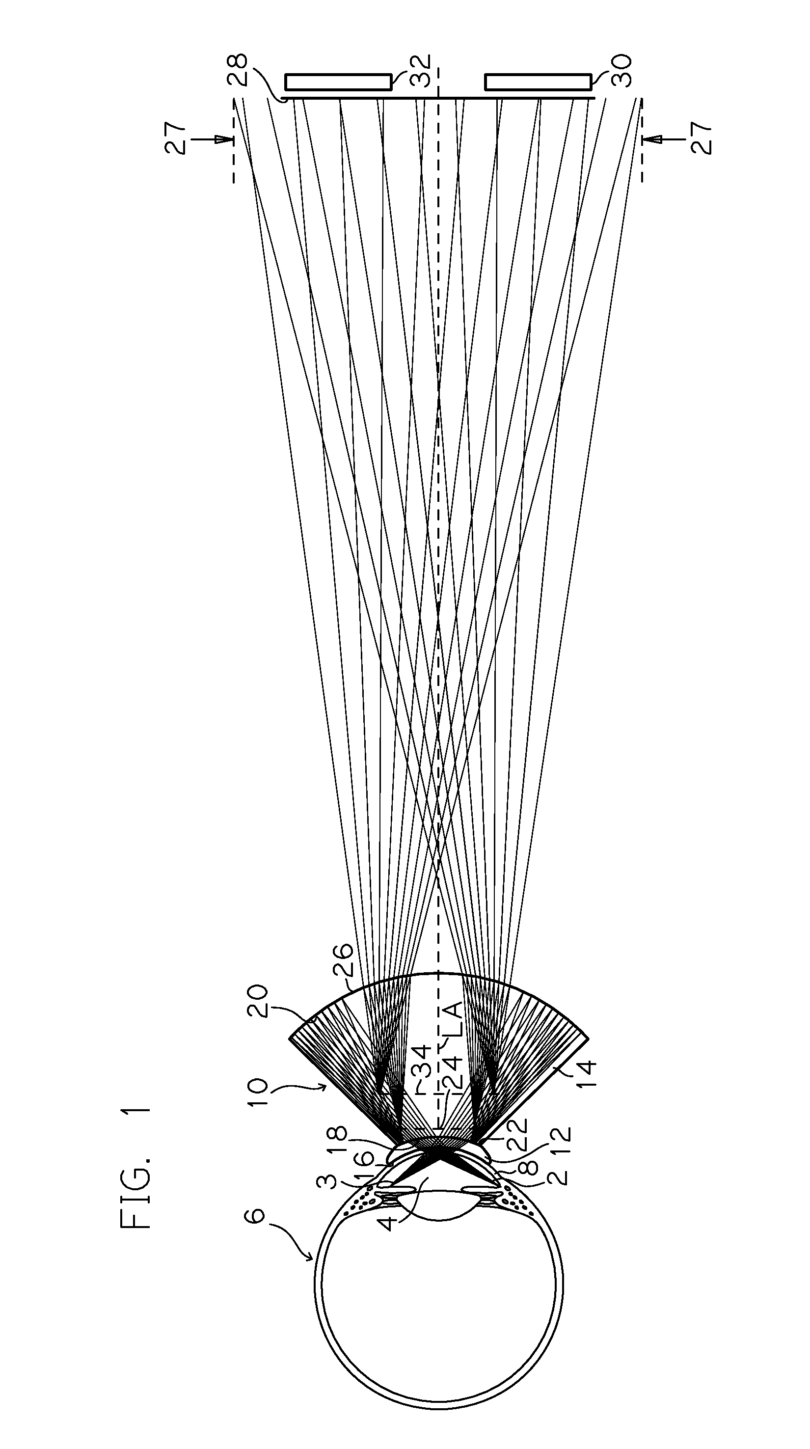
[0067]Referring to FIG. 1, there is shown a ray tracing and schematic cross-sectional view of an exemplary doublet gonioscopy lens according to the invention, wherein lens 10 comprises an optically coupled lens including posterior contacting element 12 and anterior element 14. In this embodiment the anterior reflecting surface comprises an aspheric curvature and the posterior reflecting surface comprises a spherical curvature. Posterior element 12 is made of optical quality polymethylmethacrylate with an index of refraction of approximately Nd=1.492 and an Abbe number of approximately Vd=55.3, and anterior element 14 is made of S-LAH58 optical glass (available from Ohara Corp.) having an index of refraction of approximately Nd=1.883 and an Abbe number of approximately Vd=40.8. The two elements 12 and 14 are optically coupled at their interface using a suitable optical coupling material, including one of a variety of optical adhesives known to those skilled in the art, such as those ...

second embodiment

[0088]Referring to FIG. 4, there is shown a ray tracing and schematic cross-sectional view of an exemplary single element gonioscopy lens 40 according to the invention. In this embodiment the anterior reflecting surface comprises an aspheric curvature and the posterior reflecting surface comprises a spherical surface. The lens is made of optical quality polycarbonate having an index of refraction of approximately Nd=1.585 and an Abbe number of approximately Vd=29.9.

[0089]Referring to FIG. 4, light beams 2a and 3a emanating from the prior stated iridocorneal and peripheral iris locations of anterior chamber 4a of eye 6a pass through the cornea 8a and tear layer of the eye and enter lens 40 through corneal contacting surface 42 and continue to concave annular reflecting surface 44 from which each light beam is first reflected as a positive reflection in a posterior direction. The convergent light beams proceed in their respective directions and focus at dotted line 46, which represent...

third embodiment

[0092]Referring to FIG. 5, there is shown a ray tracing and schematic cross-sectional view of an exemplary doublet gonioscopy lens according to the invention, wherein lens 60 comprises an optically coupled lens including posterior contacting element 62 and anterior element 64. In this embodiment both the posterior and anterior surfaces of lens element 64 comprise lenticulated surfaces, and all the refracting and reflecting surfaces are spherical. Both posterior element 62 and anterior element 64 are made of S-LAH59 glass (available from Ohara Corp.) with an index of refraction of approximately Nd=1.816 and an Abbe number of approximately Vd=46.6. As a cemented doublet, the two elements 62 and 64 may be adhered together at their interface using optical adhesive OP-4-20658 manufactured by Dymax Corporation.

[0093]Referring to FIG. 5, light beams 2b and 3b emanating from the stated iridocorneal and peripheral iris locations of anterior chamber 4b of eye 6b pass through the cornea 8b and...


PUM


Abstract

An inverted real image forming opthalmoscopic contact lens provides for viewing and treating structures within an eye. The lens comprises a contacting surface adapted for placement on the cornea of the eye, a concave annular anterior reflecting surface, a convex annular posterior reflecting surface, and two non-reflective portions. A first non-reflective portion is positioned along the lens axis and proximate to the convex annular posterior reflecting surface. A second non-reflective portion is positioned along the lens axis and proximate to the concave annular anterior reflecting surface. A light beam emanating from the structure of the eye enters the lens and contributes to the formation of an inverted real image of the structure through an ordered sequence of reflections of the light beam, first in a posterior direction from the anterior concave reflecting surface and next as a negative reflection in an anterior direction from the convex posterior reflecting surface.

Description

PRIORITY CLAIM[0001]This application claims priority to, and the full benefit of, U.S. Provisional Patent Application No. 61 / 135,455, titled “REAL IMAGE FORMING EYE EXAMINATION LENS UTILIZING TWO REFLECTING SURFACES WITH NON-MIRRORED CENTRAL VIEWING AREA” and filed Jul. 19, 2008, which is incorporated by reference in its entirety.BACKGROUND OF THE INVENTION[0002]1. Field of the Invention[0003]The lens of the present disclosure relates to opthalmoscopic lenses for use with the slit lamp or other biomicroscope. More particularly the invention relates to diagnostic and therapeutic gonioscopic and indirect opthalmoscopic contact lenses that incorporate two annular reflecting surfaces which combine to provide positive power contributing to the formation of an inverted real image of the examined structures of the eye within the lens or element of the lens while optimally directing the light rays proceeding from the inverted real image to the objective lens of the biomicroscope for stereos...

Claims


Application Information

Patent Timeline
IPC IPC(8): A61B3/125B29D11/00
CPCA61B3/125A61B3/117
Inventor VOLK, DONALD A.
Owner VOLK DONALD A
Why Eureka
Try Eureka