Laser surveying system and distance measuring method

Active Publication Date: 2010-04-15
KK TOPCON
View PDF3 Cites 61 Cited by
  • Summary
  • Abstract
  • Description
  • Claims
  • Application Information

AI Technical Summary

Benefits of technology

[0008]It is an object of the invention to provide a laser surveying system and a distance measuring method, by which it is possible to change a beam diameter to match the distance to be measured and to improve measurement accuracy regardless of the length of the distance to be measured.
[0011]According to the present invention, a laser surveying system comprises a light source for emitting a laser beam, a projection optical system for turning the laser beam from the light source to a parallel luminous flux, a scanning unit for projecting the luminous flux of the projected laser beam for scanning, a scanning direction detecting unit for detecting a scanning direction, a photodetection optical system for receiving a reflected light of the projected laser beam from an object to be measured, a photodetection element for performing photo-electric conversion of the reflected light received via the photodetection optical system, and a distance measuring unit for measuring a distance based on a signal from the photodetection element, wherein the projection optical system has a luminous flux diameter changing means, and a luminous flux diameter of the projected laser beam is enabled to be changed. Also, according to the present invention, there are provided a step of setting a beam diameter of a laser beam projected to match an approximate distance to an object to be measured, a step of projecting the laser beam to the object to be measured, a step of receiving a reflected light of the projected laser beam from the object to be measured, and a step of measuring a distance to the object to be measured based on the received reflection light. As a result, it is possible to have a beam diameter, which matches well the distance to be measured, and this contributes to the improvement of measurement accuracy.

Problems solved by technology

On the other hand, the near-infrared light has a long wavelength and is easily influenced by interference.
The spot size of the laser beam projected to the object to be measured is increased, and this leads to the decrease in the measurement accuracy.
In this respect, in the conventional type laser surveying system, there has been a tendency that error is increased when the actual distance to be measured is deviated from the standard measurement distance.
In particular, in case near-infrared light is used as the distance measuring light, the spreading angle is big, and there has been a tendency that bigger error is caused when the distance to be measured is deviated from the standard measurement distance.

Method used


Image

  • Laser surveying system and distance measuring method
  • Laser surveying system and distance measuring method
  • Laser surveying system and distance measuring method

Examples


Embodiment Construction

[0018]Description will be given below on the best mode for carrying out the invention by referring to the attached drawings.

[0019]As a type of a laser surveying system, a 3-demensional measuring system is known, which is so-called a laser scanner. According to the 3-dimensional measuring system, a pulsed measuring beam is projected for scanning to an object to be measured and a distance is measured based on a reflection light from the object to be measured. Then, three-dimensional measurement of the object to be measured is performed based on the value of the measured distance and the value of projection angle, and point group data is obtained.

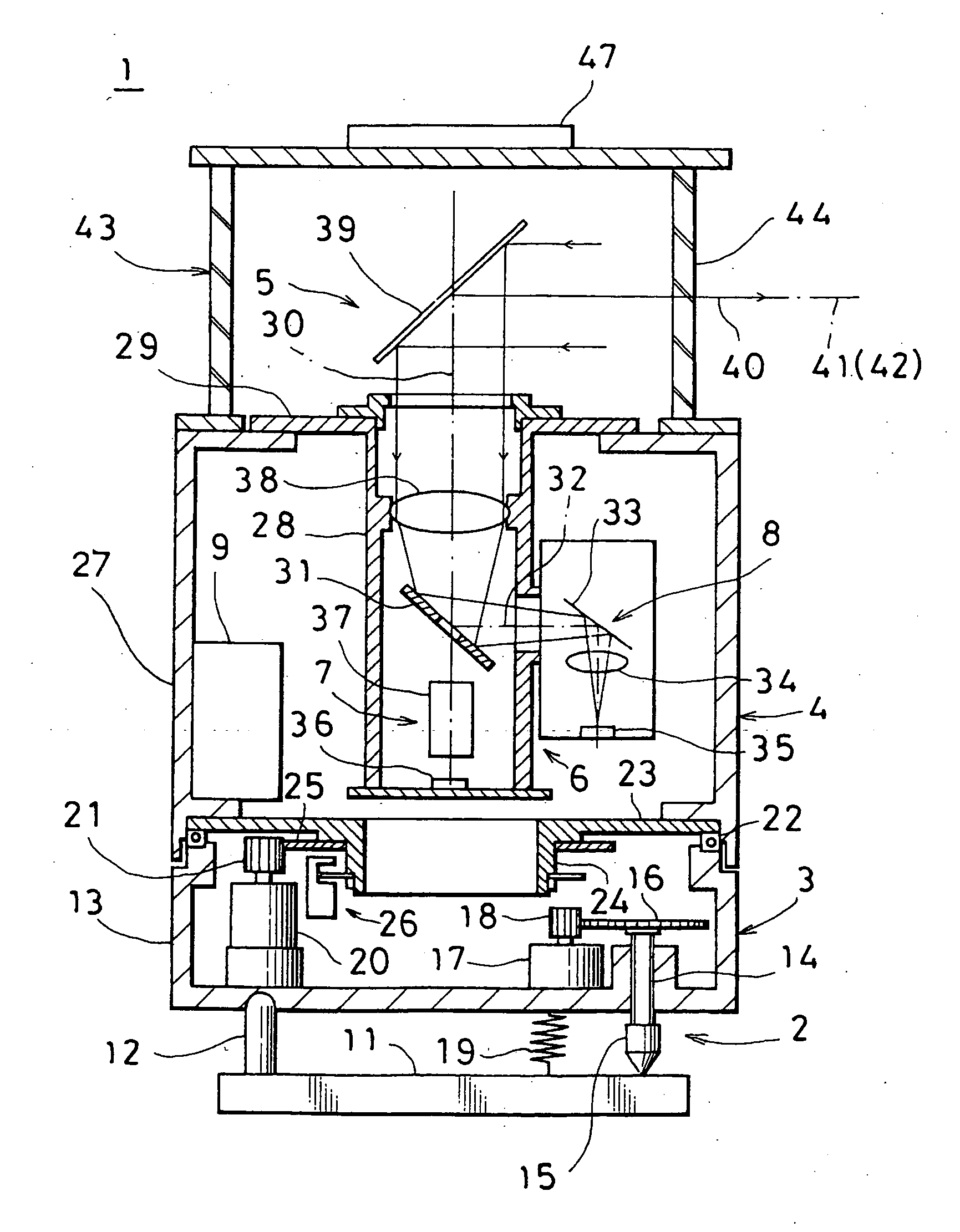
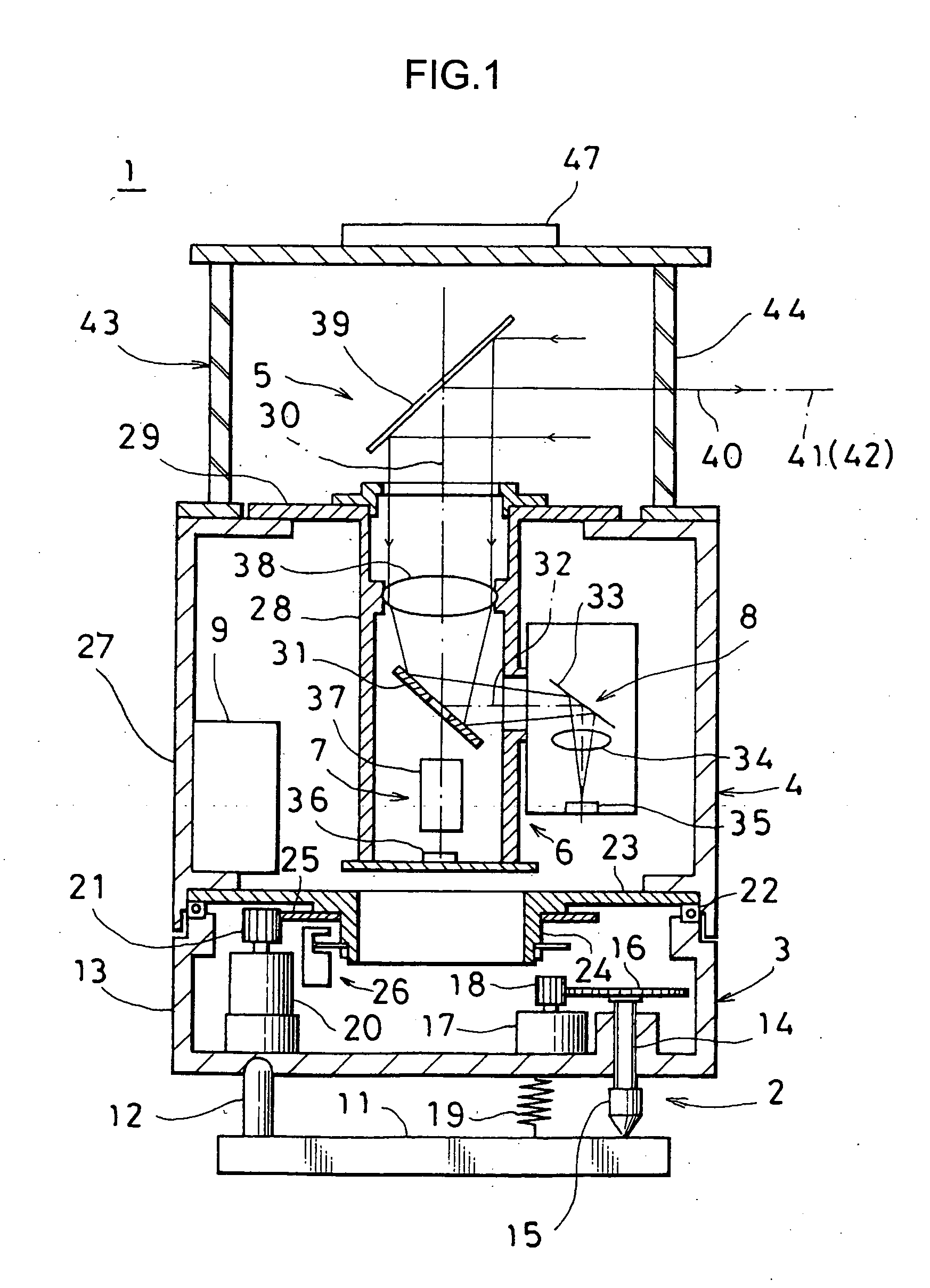
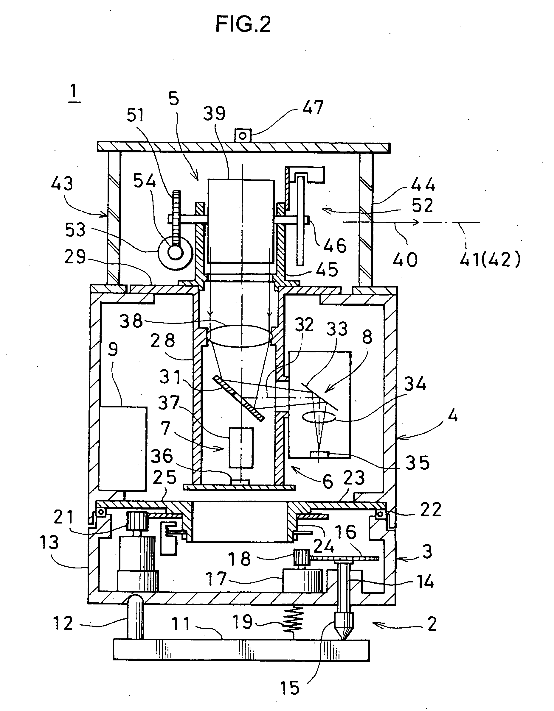
[0020]FIG. 1 and FIG. 2 each represents a case where the present invention is carried out on a laser scanner 1.

[0021]The laser scanner 1 primarily comprises a leveling unit 2, a rotary mechanism 3 installed on the leveling unit 2, a measuring system main unit 4 rotatably supported on the rotary mechanism 3, and a scanner unit 5 mounted on the ...


PUM


Abstract

A laser surveying system, comprising a light source for emitting a laser beam, a projection optical system for turning the laser beam from the light source to a parallel luminous flux, a scanning unit for projecting the luminous flux of the projected laser beam for scanning, a scanning direction detecting unit for detecting a scanning direction, a photodetection optical system for receiving a reflected light of the projected laser beam from an object to be measured, a photodetection element for performing photo-electric conversion of the reflected light received via the photodetection optical system, and a distance measuring unit for measuring a distance based on a signal from the photodetection element, wherein the projection optical system has a luminous flux diameter changing means, and a luminous flux diameter of the projected laser beam is enabled to be changed.

Description

BACKGROUND OF THE INVENTION[0001]The present invention relates to a laser surveying system and a distance measuring method for projecting a laser beam to an object to be measured and for measuring a distance by receiving a light reflected from the object to be measured.[0002]As an electro-optical distance measuring system, a laser surveying system is known, which projects a laser beam as a distance measuring light to an object to be measured and measures a distance to the object to be measured by using a light reflected from the object to be measured.[0003]When a laser beam is projected to an object to be measured and electro-optical distance measurement is performed, a point on the object to be measured where the laser beam is projected is not necessarily on a flat surface, and the point may be an edge where flat surfaces cross each other. Because the laser beam has a certain spreading, a luminous flux of the beam has an area, and the condition on the projected surface of the objec...

Claims


Application Information

Patent Timeline
IPC IPC(8): G01C3/08
CPCG01C3/08G01S17/42G01S17/10G01S7/4814
Inventor KUMAGAI, KAORUYOSHINO, KENICHIROTANAKA, YASUSHIISHINABE, IKUO
Owner KK TOPCON
Why Eureka
Try Eureka