
Optical Fiber Cable Assembly

a technology of optical fiber cable and assembly, which is applied in the direction of optics, fibre mechanical structures, instruments, etc., can solve the problems of limited protection, little protection, and the available furcation tubes do not adequately protect the length of fiber extending from the cable, so as to reduce facilitate the handling, and protect the structure. , the effect of reducing the flexibility of the furcation leg

Inactive Publication Date: 2010-04-15
DRAKA COMTEQ BV
View PDF33 Cites 127 Cited by
  • Summary
  • Abstract
  • Description
  • Claims
  • Application Information

AI Technical Summary

Benefits of technology

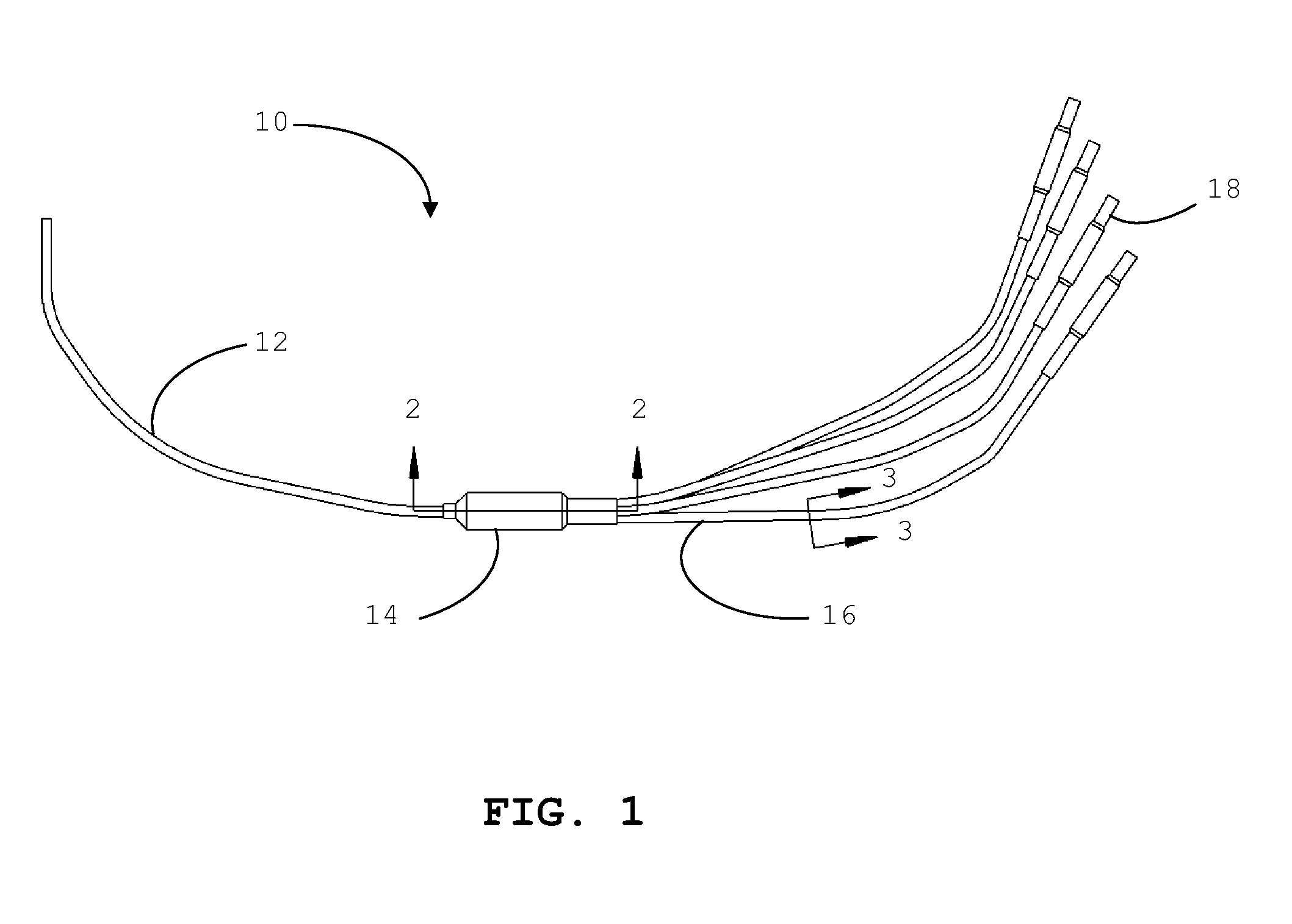
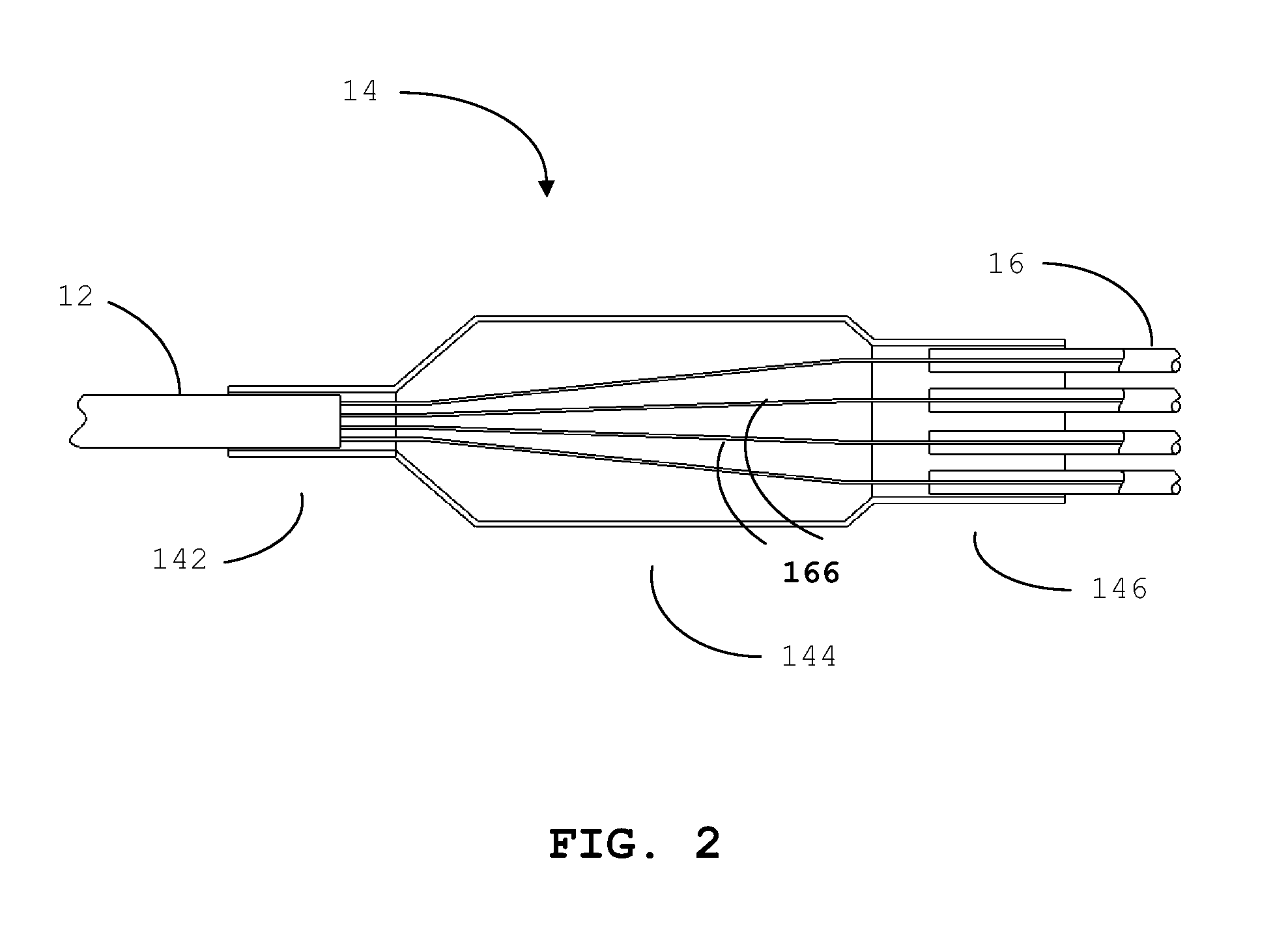
[0019]The furcation legs further include (i) a buffer tube surrounding at least one of the optical fibers, (ii) strength members surrounding the buffer tube, and (iii) a protective jacket surrounding the strength members. The furcation legs of the present invention exhibit improved tensile properties and can have a tensile rating of at least about 50 pounds (lbf), such as 75-100 pounds (lbf) or more.
[0020]Despite significantly improved tensile properties, the furcation legs of the present invention may also have small diameters. In various exemplary embodiments, the furcation legs can possess, for example, a jacket outer diameter of up to about 5.0 millimeters and a buffer tube outer diameter of up to about 2.0 millimeters. The inner diameter of the buffer tube is designed such that the optical fiber can be inserted into the tube over several feet during the assembly of a furcation leg and its ruggedized connector. Thus, the furcation legs of the present invention can be readily connectorized to various optical connectors and yet still exhibit desirable tensile properties.
[0021]The furcation legs of the present invention further exhibit other desirable properties for outdoor applications. For example, the furcation legs can exhibit minimal or reduced longitudinal shrinkage when exposed to the extreme temperatures and / or temperature cycling encountered in some outdoor installations.
[0024]The strength members of the furcation legs may be formed of any suitable high-strength material, such as aramid material (i.e., aromatic polyamides), fiberglass, polyester material, or a combination thereof. In exemplary embodiments of the present invention, the strength members may be aramid yarn helically wound about a buffer tube. Such flexible strength members can provide tensile strength needed to survive outdoor environmental factors (e.g., wind, ice, snow, and rain) without substantially diminishing or reducing the flexibility of the furcation leg. This flexibility facilitates ease of handling for making connections and disconnections of the ruggedized connectors. The combination of a furcation leg's buffer tube, strength elements, and outer jacket can also provide protection to the optical fiber from compression forces resulting from handling, as well as from the outdoor elements (e.g., rain, sleet, snow, and wind).
[0025]Thus, in contrast to conventional furcation tubing, the furcation legs of the present invention can provide sufficient strength, protection, and structural rigidity along the length of the optical fibers so that the furcated optical fibers are suitable for many outdoor applications. Yet despite the improved tensile and structural properties, the furcation legs still exhibit sufficient flexibility so that the legs can be readily connectorized and used in confined spaces in the field.

Problems solved by technology

These conventional furcation tubes are typically solid or spiral low-modulus polymeric tubes that provide a flexible means for grouping and handling fibers while providing little protection.
Alternatively, in the case of some stranded loose-tube optical-fiber-cable designs, the buffer tube containing the fiber can be extended from the cable along with the fiber to provide the same fiber grouping and handling benefits with very limited protection (i.e., because of the low modulus of the tubes).
The currently available buffer tubes in loose tube cables and commercially available furcation tubes do not adequately protect the length of fiber extending from the cable to the ruggedized connector in the outdoor environment.
Multi-fiber cables using currently available technology would require additional enclosures, cabinets, terminals, or buildings to adequately protect this furcated section of the assembly, thereby diminishing the benefit of ruggedized connectors.

Method used


Image

  • Optical Fiber Cable Assembly
  • Optical Fiber Cable Assembly
  • Optical Fiber Cable Assembly

Examples


Embodiment Construction

[0035]The present invention now will be described more fully hereinafter with reference to the accompanying drawings, in which some, but not all, embodiments of the present invention are shown. Indeed, this invention may be embodied in many different forms and should not be construed as limited to the embodiments set forth herein; rather, these embodiments are provided so that this disclosure will satisfy applicable legal requirements. Like numbers refer to like elements throughout.

[0036]The terminology used herein is for the purpose of describing particular embodiments only and is not intended to be limiting of the present invention. As used herein the term “and / or” includes any and all combinations of one or more of the associated listed items. As used herein, the singular forms “a,”“an” and “the” are intended to include the plural forms as well, unless the context clearly indicates otherwise.

[0037]Embodiments of the present invention are described herein with reference to various...


PUM


Abstract

The present invention provides optical fiber communication cable assemblies useful for separating and conveying individual fibers from a multiple optical fiber cable to connectors in a protective manner. The optical fiber cable assembly is suitable for outdoor use and includes a (i) cable with multiple optical fibers; (ii) a furcation unit attached to the cable for directing individual optical fibers from the cable to furcation legs; and (iii) multiple furcation legs receiving at least one of the optical fibers. The furcation legs include (i) a buffer tube surrounding the optical fiber; (ii) strength members surrounding the buffer tube; and (iii) a jacket surrounding the strength members. The furcation legs typically exhibit a tensile rating of at least about 50 pounds (lbf), more typically 100 pounds (lbf) or more. Moreover, the furcation legs typically exhibit total shrinkage of less than about 2 percent when cycled from +23° C. to −40° C. to +70° C. to −40° C.

Description

CROSS REFERENCE TO PRIORITY APPLICATIONS[0001]This application claims the benefit of U.S. Patent Application No. 61 / 096,545 for an “Optical Fiber Cable Assembly” (filed Sep. 12, 2008), and U.S. Patent Application No. 61 / 139,228 for an “Optical Fiber Cable Assembly” (filed Dec. 19, 2008), each of which is incorporated by reference in its entirety.FIELD OF THE INVENTION[0002]This invention relates generally to optical fiber cable assemblies and, more particularly, to optical fiber cable assemblies for separating and conveying individual fibers from a multiple optical fiber cable to connectors in a protective manner.BACKGROUND OF THE INVENTION[0003]Optical fiber systems are well known and offer several advantages, including a high bandwidth for signal transmission, low noise operation, and inherent immunity to electromagnetic interference. Because of these advantages, optical fibers are increasingly used in a variety of communications applications, including voice, video, and data tran...

Claims


Application Information

Patent Timeline
IPC IPC(8): G02B6/44G02B6/36
CPCG02B6/4471
Inventor BARKER, JEFFREY SCOTTBAIRD, PAUL RANDALLRASMUSSEN, III, THOMAS ANDREW
Owner DRAKA COMTEQ BV
Learn More