Method and apparatus for real-time feedback control of electrical manipulation of droplets on chip

Active Publication Date: 2010-04-22
RGT UNIV OF CALIFORNIA
View PDF7 Cites 297 Cited by
  • Summary
  • Abstract
  • Description
  • Claims
  • Application Information

AI Technical Summary

Benefits of technology

[0013]In one aspect of the invention, a device for generating droplets includes a substrate comprising a reservoir site configured to hold a liquid and comprising a first electrode, a droplet creation site comprising a second electrode, and a droplet separation site comprising a third electrode disposed between the reservoir site and the droplet creation site. The device includes control circuitry operatively coupled to the first, second, and third electrodes, the control circuitry configured to measure the droplet volume (via capacitance measurements) of at least the second electrode, the control circuitry further being configured to independently adjust an applied voltage to the first, second, and/or third electrodes based at least in part on the measured droplet volume. The control circuitry may be configured to adjust the voltage of the second electrode to maintain a target droplet volume. The reservoir site may include a droplet that is subsequently split. It should be understood that the reservoir may be isolated, containing a droplet of wide volume range, or may be communicating with an input source on or off chip. If the reservoir is small enough, generation of a droplet from the reservoir is equivalent to splitting a droplet into two. It should also be understood that the first, second, and third electrodes may include a group or set of multiple electrodes. It should further be understood that, although the invention is written primarily for a liquid droplet in air, the same invention applies to a liquid droplet in any immiscible fluids (e.g., water in oil) as well as a gas bubble in a liquid.
[0014]In another aspect of the invention, a device for generating droplets includes a substrate comprising a reservoir site configured to hold a liquid and comprising a first electrode, a droplet creation site comprising a second electrode, and a droplet separation site comprising a third electrode. The device further includes control circuitry operatively coupled to the first, second, and third electrodes, the control circuitry configured to measure the droplet volume (via capacitance) of at least the second electrode while simultaneously being configured to independently adjust an applied voltage to one or more of the first, second, and third electrodes based at least in part on the measured droplet volume, wherein when a driving voltage is applied to the first electrode fluid is drawn toward and onto the first electrode, when a driving voltage is applied to the second electrode fluid is drawn toward and onto the second electrode, and when a driving voltage is applied to the third electrode fluid is drawn onto the third electrode. The device permits real-time adjustment of the putative droplet size to permit droplet generation of uniform sizes (e.g., volumes). Alternatively, the feedback system may be used to generate droplets having a user-defined size. This user-defined size includes droplets having sizes that are much s

Problems solved by technology

These types of pumps utilize moving parts which may present problems related to manufacturability, complexity, reliability, power consumption and high operating voltage.
Electrokinetic mechanisms (i.e., electrophoresis and electroosmosis) are limited because certain operating liquids contain ionic particles.
Moreover, they require high voltage and high e

Method used


Image

  • Method and apparatus for real-time feedback control of electrical manipulation of droplets on chip
  • Method and apparatus for real-time feedback control of electrical manipulation of droplets on chip
  • Method and apparatus for real-time feedback control of electrical manipulation of droplets on chip

Examples


Embodiment Construction

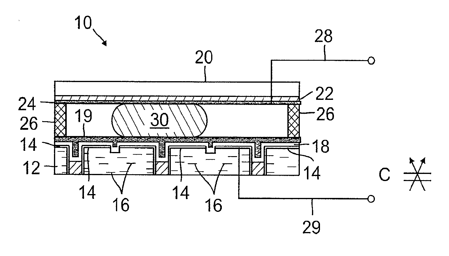
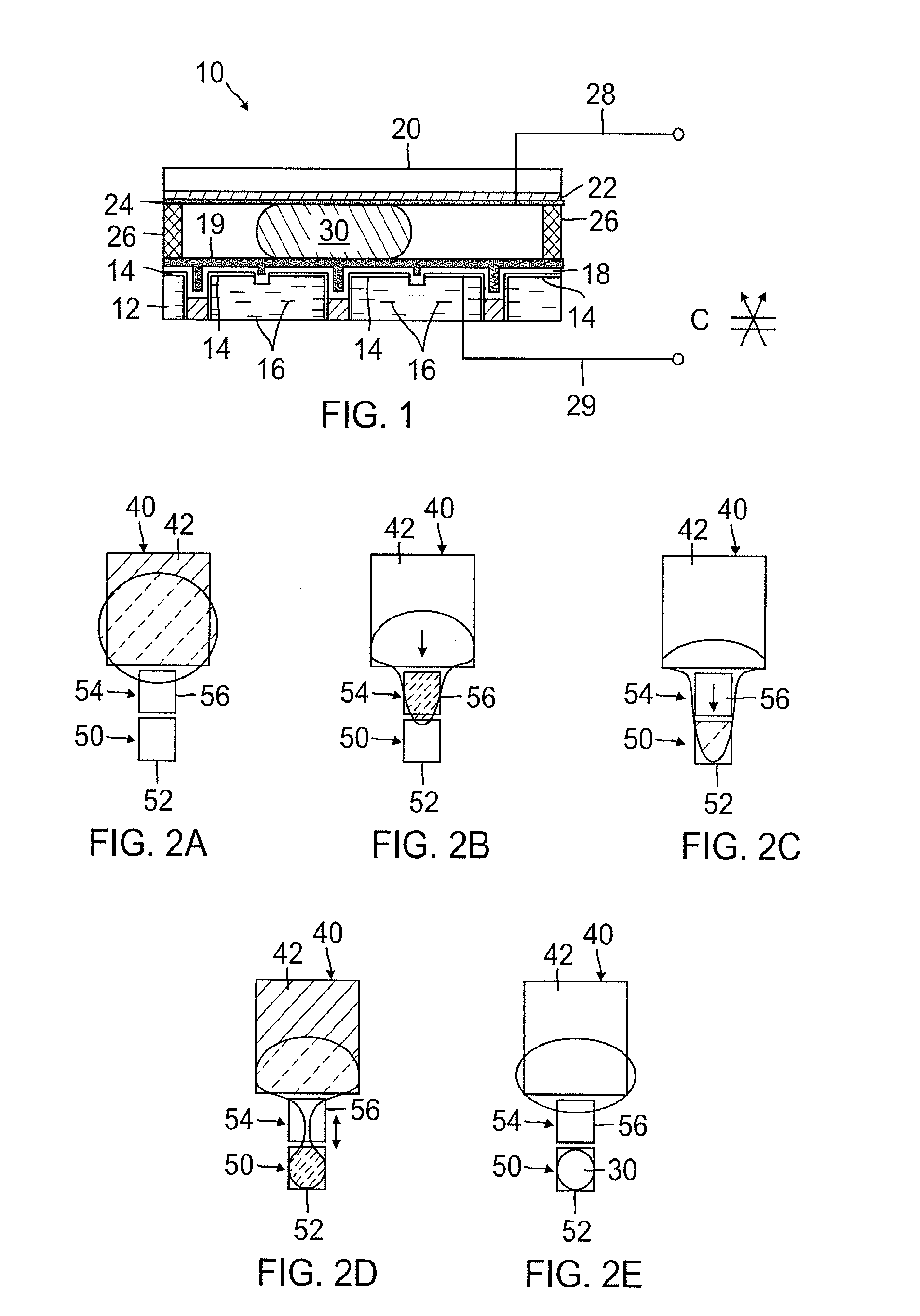
[0033]FIG. 1 schematically illustrates a cross-sectional view of a microfluidic device 10 that can be used in accordance with the invention. The microfluidic device 10 may include an electrowetting-on-dielectric (EWOD) based device 10. For example, the microfluidic device 10 may include an EWOD chip. As seen in FIG. 1, the EWOD chip 10 is made of a substrate 12 that may have one layer or multi-layer electric lines in it, printed circuit board (PCB) being one example. The substrate 12 includes a number of electrodes 14 made from an electrically conductive material (e.g., copper). The PCB substrate 12 may include multiple copper layers 16 (e.g., four layers) within the substrate to allow direct referencing for two-dimensional electrode arrays. For better performance, the PCB substrate 12 may be then lapped, polished by chemical-mechanical polishing (CMP), and a coating of dielectric 18 is deposited or otherwise applied. The dielectric layer 18 may include a 8000 Å layer of Parylene C....


PUM

PropertyMeasurementUnit
Sizeaaaaaaaaaa
Volumeaaaaaaaaaa
Electric potential / voltageaaaaaaaaaa

Abstract

A device for generating droplets includes a substrate comprising a reservoir site configured to hold a liquid and including a first electrode, a droplet creation site including a second electrode, and droplet separation site disposed between the reservoir site and the droplet creation site and containing an electrode. The device includes control circuitry operatively coupled to the first, second, and third electrodes. The control circuitry is configured to measure the fluid volume on the electrodes and independently adjust an applied voltage to increase/decrease the quantity of fluid. The device can move fluid onto the creation site or back onto to the reservoir site. When the fluid volume is at the desired value or range, a driving voltage is delivered to the first and second electrodes to form a new droplet. The device may generate droplets having a uniform or user-defined size smaller than the electrode.

Description

REFERENCE TO RELATED APPLICATION [0001]This Application claims priority to U.S. Provisional Patent Application No. 60 / 864,061 filed on Nov. 2, 2006. U.S. patent application Ser. No. 60 / 864,061 is incorporated by reference as if set forth fully herein.FEDERALLY-SPONSORED RESEARCH AND DEVELOPMENT [0002]The U.S. Government may have a paid-up license in this invention and the right in limited circumstances to require the patent owner to license others on reasonable terms as provided for by the terms of Grant No. NCC2-1364 by the National Aeronautics and Space Administration.FIELD OF THE INVENTION [0003]The field of the invention generally relates devices and methods for generating droplets on a microfluidic platform operated by electrical manipulation such as electrowetting-on-dielectric (EWOD). More specifically, the field of the invention relates to feedback devices and methods for generating droplets having uniform or controlled volumes.BACKGROUND OF THE INVENTION[0004]Microfluidic s...

Claims


Application Information

Patent Timeline
IPC IPC(8): B01F3/08H04N1/034B01D57/02
CPCB01F13/0071B01F13/0076B01L3/502792B01L2200/0605B01L2400/0427B01L2300/0816B01L2300/0819B01L2300/0864B01L2300/089B01L2200/143B01F33/3031B01F33/3021
Inventor KIM, CHANG-JINGONG, JIAN
Owner RGT UNIV OF CALIFORNIA
Why Eureka
Try Eureka