
Weatherproof building envelope

a building envelope and weatherproof technology, applied in photovoltaics, solar heat collectors for particular environments, sustainable buildings, etc., can solve the problems of complex roof integration structures, unsatisfactory functionality and heat yield, and affect the economic efficiency of combined current/heat recovery

Active Publication Date: 2010-04-29
AMYT ENERGY HLDG LLC
View PDF29 Cites 5 Cited by
  • Summary
  • Abstract
  • Description
  • Claims
  • Application Information

AI Technical Summary

Benefits of technology

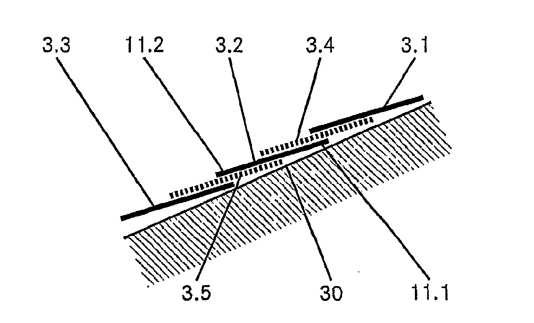
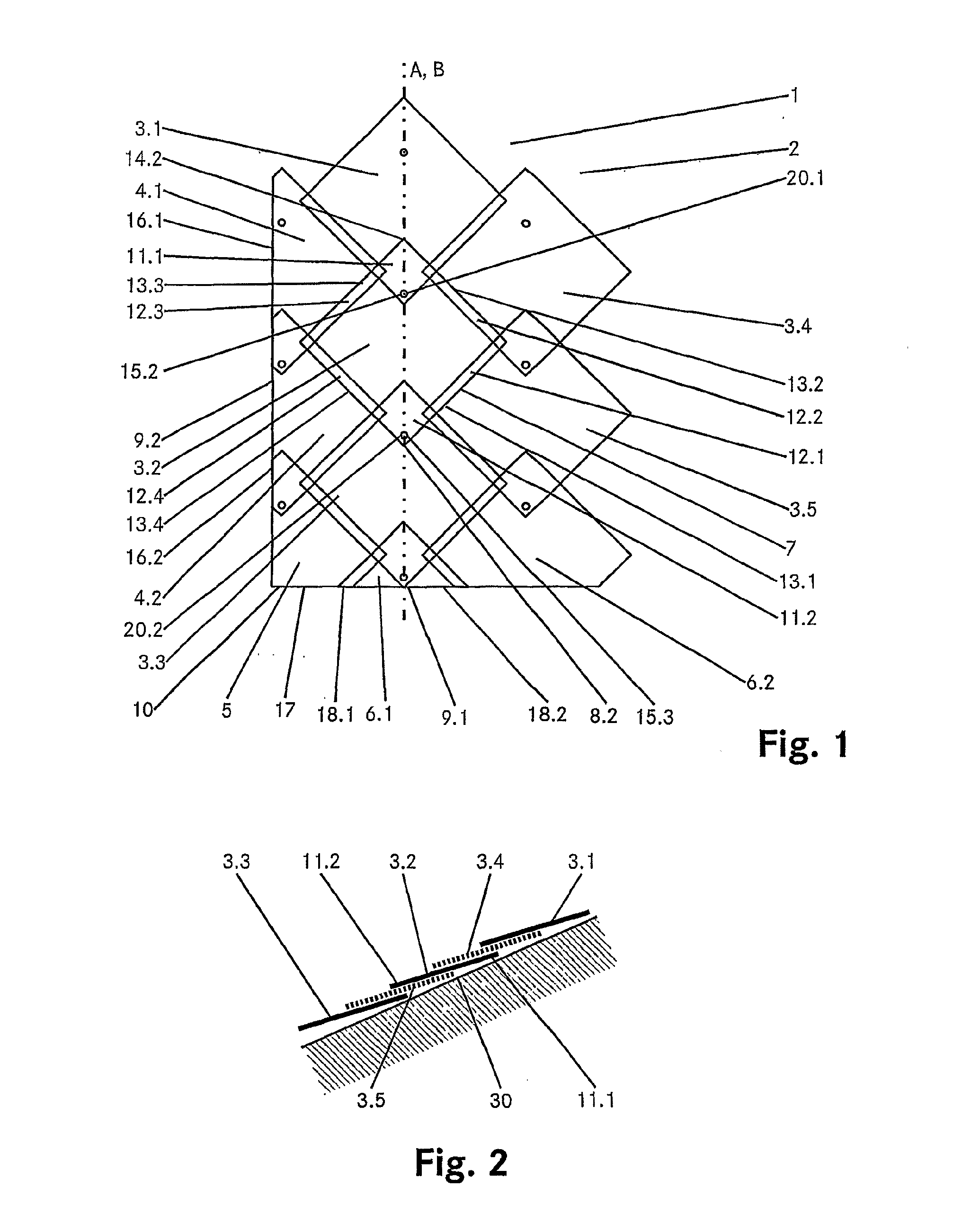
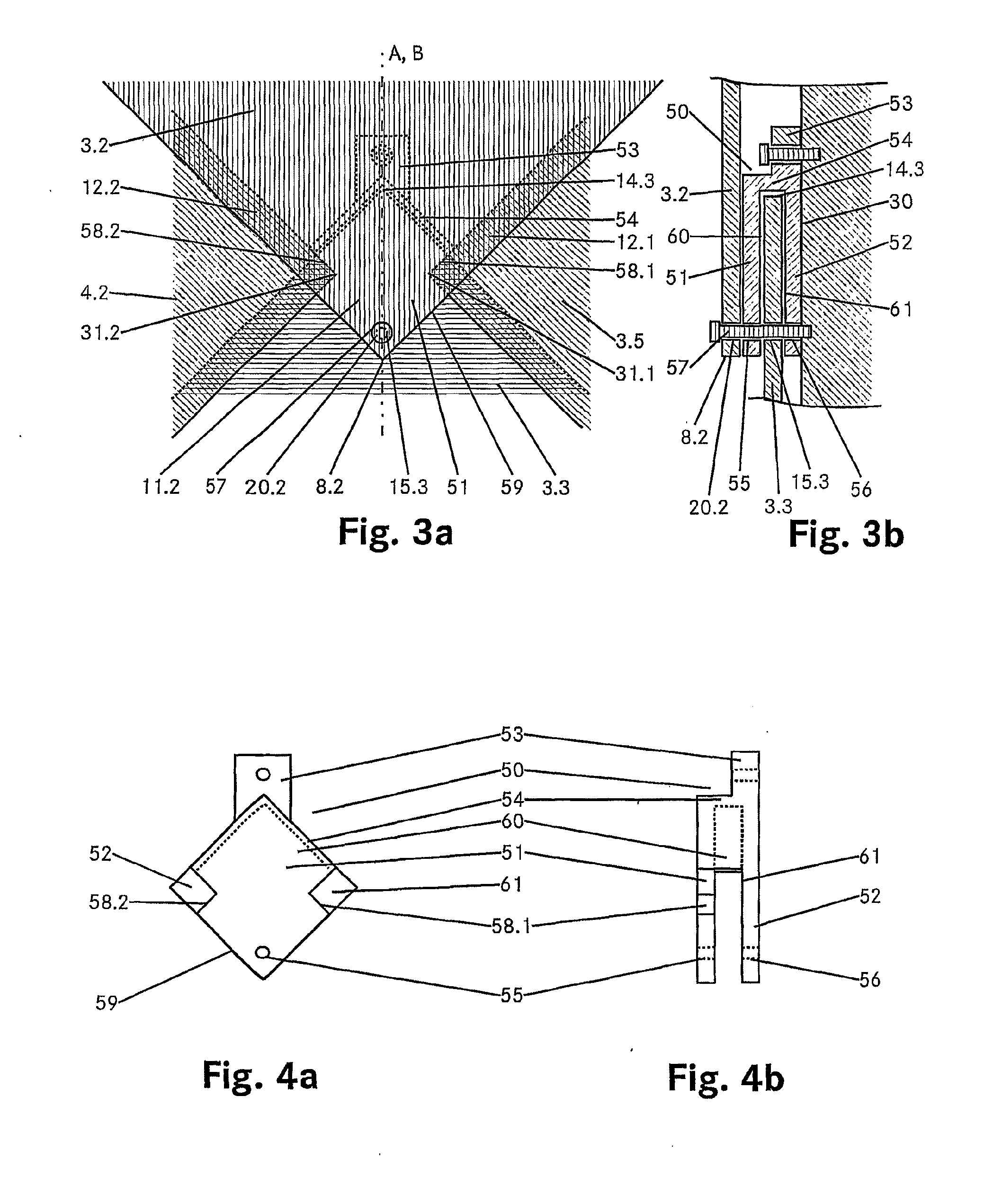
[0014]The system as claimed in the invention is simple in structure and can implement different technical functions. Thus the panels can be equipped with solar cells to obtain electrical energy. They can also be used solely to obtain thermal energy. It is important that the system is fundamentally designed such that the arrangement of panels can be varied from application to application, so that for given panel dimensions the most varied (individual) dimensions of the building envelope can also be implemented in a weatherproof and aesthetically satisfactory manner. In particular, the pattern of “side by side” panels laid square (“bathroom tile pattern”) which many considered unattractive can be avoided.
[0057]Glass roof panel with a simple roof function. It consists of a glass panel hardened on the front with a film laminated onto the back for coloring, and fasteners and / or pressing elements on the four corners. For this function however also other materials can be used with the same geometrical structure and fastening technology.

Problems solved by technology

The functionality and heat yield are unsatisfactory, likewise the aesthetic circumstances and the suitability for building standardized rooves.
They generally also have complex structures for roof integration.
All the aforementioned factors adversely affect the economic efficiency of combined current / heat recovery.

Method used


Image

  • Weatherproof building envelope
  • Weatherproof building envelope
  • Weatherproof building envelope

Examples


Embodiment Construction

[0012]The object of the invention is to devise a weatherproof building envelope which belongs to the initially mentioned technical domain, with several quadrilateral weatherproof panels which allows use of solar energy, and at the same time is aesthetically pleasing.

[0013]This object is achieved by the features of claim 1. As claimed in the invention, the panels are installed with respect to the line of slope in a diagonal position with scale-like mutual overlapping. The overlapping is dimensioned such that water cannot travel through to the inside under the overlapping. As a result of the diagonal position the panels which overlap transversely to the line of slope in the edge region are offset to one another. The panels are connected to a bearing structure on one corner area which is underneath with respect to the line of slope. In the indicated corner region of the panel there is furthermore a sealing element which closes the gap between the panels arranged transversely to the mai...


PUM


Abstract

The invention relates to a weatherproof building shell, especially a pitched roof, comprising a plurality of rectangular weatherproof shingles which are laid diagonally to mutually overlap in a scale-type fashion in relation to a line of slope. Shingles that overlap in an edge zone at a right angle to the line of slope are set off in relation to each other. The shingles are connected to a supporting structure in a lower corner zone of the shingle in relation to a line of slope, respective sealing elements being arranged on said corner zone of the shingle and obturating a gap between shingles that are arranged on the same level at a right angle to the main direction. The rectangular shingles have respective through-openings for fastening elements in two opposite corner zones so that the shingles are connected to the supporting structure in their lower and upper corner zones in relation to the main direction.

Description

TECHNICAL DOMAIN[0001]The invention relates to a weatherproof building envelope, especially a sloped roof, with several quadrilateral weatherproof panels. Furthermore the invention relates to a panel for a building envelope and a kit for preparing a building envelope.PRIOR ART[0002]The use of solar radiation which is incident daily on rooves and facades of inhabited or uninhabited buildings for obtaining energy in the form of electric current and heat has already acquired great importance.[0003]Due to the finite nature of fossil energy sources and also uranium, the development of inexhaustible energy sources such as that of the sun is of great importance for our future energy supply.[0004]The reduction of burning and the increased replacement of fossil energy sources are however also necessary for ecological reasons.[0005]Development in recent years has shown that large-scale recovery of solar power and heat is possible. Already the annual production of solar cells for generating po...

Claims


Application Information

Patent Timeline
Patent Type & Authority Applications(United States)
IPC IPC(8): E04B7/02E04D13/18E04D1/34
CPCE04D1/125E04D1/16F24J2002/0061H02S20/23Y02E10/50E04D2003/3615Y02B10/12F24S2020/13Y02B10/10E04D1/30E04D1/29E04D13/00E04F13/21E04D3/36
Inventor POSNANSKY, MARIO
Owner AMYT ENERGY HLDG LLC
Learn More