High-pressure pump for delivering fuel comprising a torsion-decoupled compression spring element in the plunger unit

a technology of compression spring and plunger unit, which is applied in the direction of piston pumps, positive displacement liquid engines, machines/engines, etc., to achieve the effects of high hardness, low coefficient of friction, and high adhesion strength

Inactive Publication Date: 2010-04-29
ROBERT BOSCH GMBH
View PDF7 Cites 5 Cited by
  • Summary
  • Abstract
  • Description
  • Claims
  • Application Information

AI Technical Summary

Benefits of technology

[0009]According to an advantageous modification of the arrangement of the cam follower device includes a pressure disk element that the compression spring element is brought to rest against, with at least one flat surface of the pressure disk element constituting the contact surface with the friction-minimized surface coating. The pressure disk element is embodied as annular and has two opposing flat surfaces so that one flat surface abuts the contact surface in the cam follower guide and the other flat surface abuts the end of the compression spring element. To minimize the friction and therefore to decouple the torsion between the compression spring element and the cam follower guide, either the first flat surface, the opposing flat surface, or both flat surfaces of the pressure disk element can be provided with a friction-minimized surface coating. The compression disk element, however, can also be attached in a torsion-preventing fashion to one end of the compression spring element, thus allowing a definite sliding motion of the opposing flat surface of the pressure disk element in relation to the cam follower guide. If the compression spring element is compressed, then a torsion can be produced in the compression spring element, which is compensated for between the pressure disk element and the cam follower guide.
[0012]The friction-minimized surface coating is advantageously applied to the at least one contact surface by means of a PVD method, a CVD method, a galvanic method, or a chemical method. It is also possible for the friction-minimized surface coating to include a sliding lacquer and / or a dry lubricant applied to the contact surface. The friction-minimized surface coating can also be a hard material coating such as a titanium oxide coating, a zirconium oxide coating, a silicon oxide coating, a titanium carbide coating, or a titanium nitrite coating. It is also possible to provide innovative PVD / hard material coatings such as TiMgN coatings. A combination of friction-minimized surface coatings and a surface layer treatment of the respective contact surface is another advantageous possibility within the scope of the present invention. Titanium carbide coatings, which feature a very high degree of hardness, paired with a low coefficient of friction and extremely high adhesion strength, are particularly advantageous. By contrast, titanium nitrite coatings feature a high degree of hardness, high durability, and a very low build-up tendency, making it possible to avoid the occurrence of fretting and coating buildup. Favorable corrosion and oxidation properties are also advantageous.
[0013]The cam follower device, which includes the compression spring element, is situated inside the pump body, which is filled with fuel. For this reason, the fuel can function as a lubricant so that the surface coating cooperates with the lubricating action of the fuel. For this reason, the surface coating should have a corresponding resistance to fuel, in particular diesel fuel. Another possible surface coating can be a titanium aluminum nitrite coating; another possible hard material coating is a chromium nitrite coating. These coatings particularly feature a very high chemical and thermal stability; the chromium nitrite coating in particular has a low adhesion tendency since the arrangement of the compression spring element operatively connected to the pressure disk element and / or the spring washer element can have high local surface pressures, so that a low adhesion tendency is advantageous.
[0015]In order to also be able to utilize the advantages of the embodiment of the friction-minimized surface coating according to the invention for other surfaces subjected to stress, it is possible within the scope of the present invention for the entire compression spring element, the entire cam follower guide, the entire pressure disk element, and the spring washer element to be completely covered with a surface coating. The cam follower guide in particular slides in a guide bore inside the pump body or the cylinder head so that it is also advantageous to provide the entire components with a coating.

Problems solved by technology

When a contact surface is provided with a friction-minimized surface coating, the torsion of the compression spring element that accompanies its compression cannot be transmitted to the cam follower device, so that the torsion of the compression spring element can no longer cause a torsion of the cam follower device and therefore a torsion of the feeler element on the cam geometry.

Method used


Image

  • High-pressure pump for delivering fuel comprising a torsion-decoupled compression spring element in the plunger unit
  • High-pressure pump for delivering fuel comprising a torsion-decoupled compression spring element in the plunger unit
  • High-pressure pump for delivering fuel comprising a torsion-decoupled compression spring element in the plunger unit

Examples


Embodiment Construction

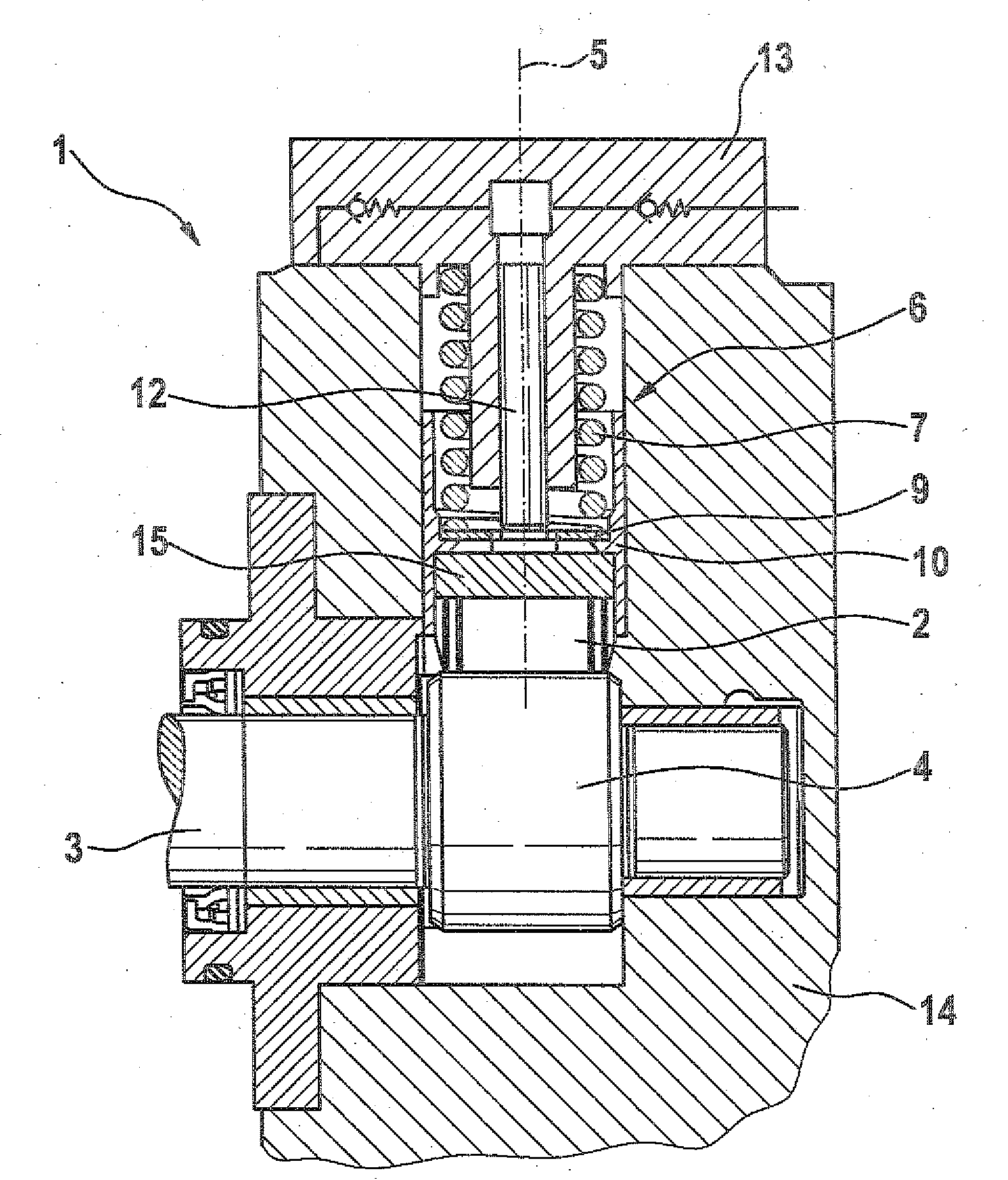
[0017]FIG. 1 is a cross-sectional view of a high-pressure pump with a cam follower device, a compression spring element, a cam follower guide with an inserted roller shoe, and a pressure disk element situated between the compression spring element and the cam follower guide;

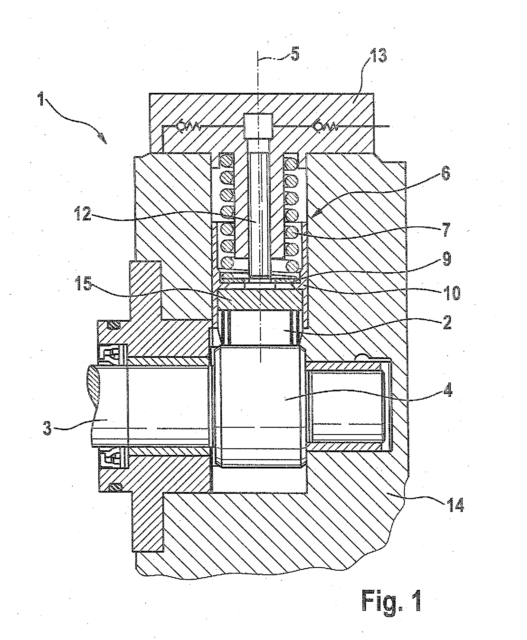
[0018]FIG. 2 is a cross-sectional view of the pressure disk element according to the invention, with a first and second contact surface; and

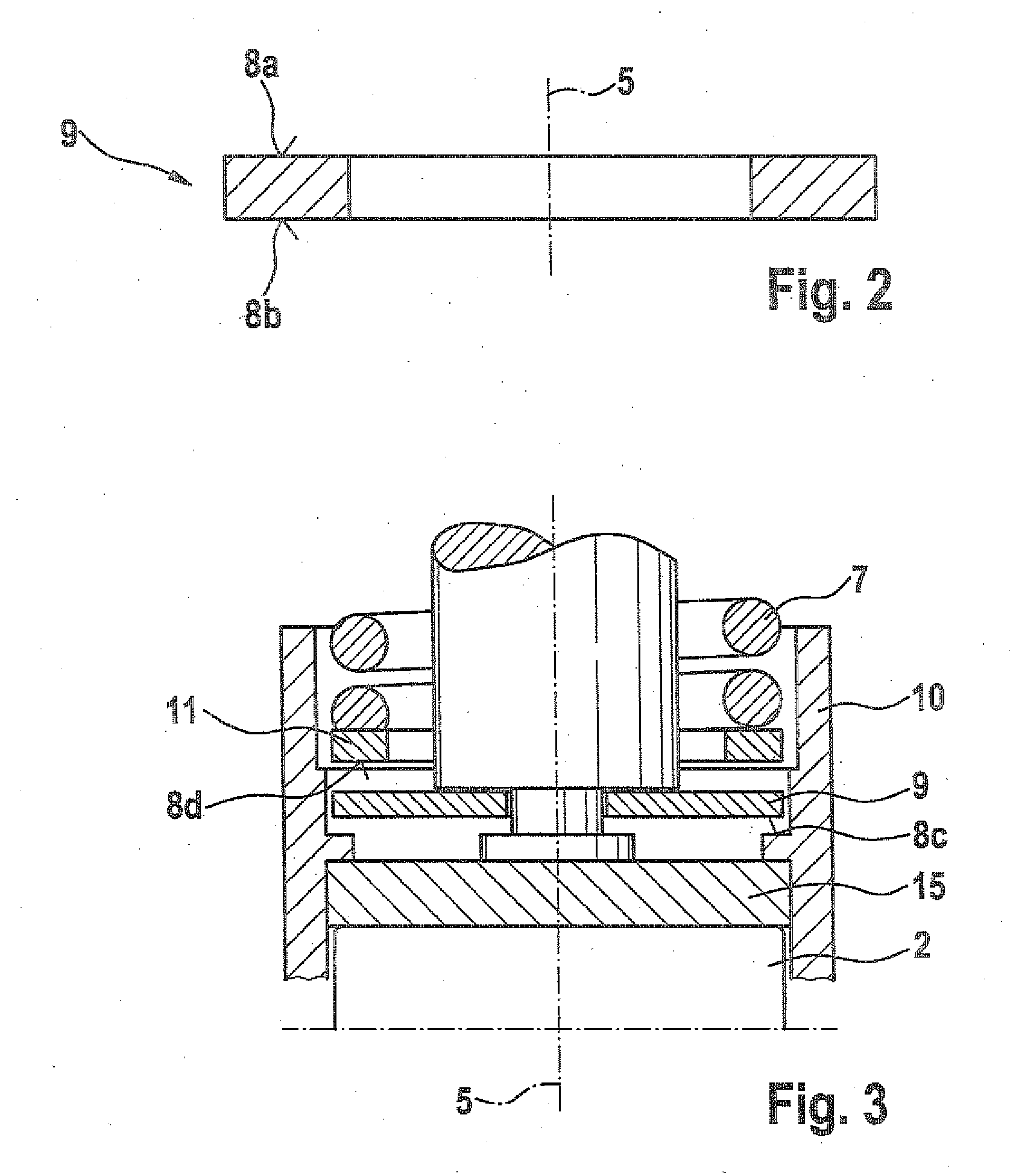
[0019]FIG. 3 is a cross-sectional view of the arrangement of the cam follower device with the respective contact surfaces according to the invention; the compression spring element, the pressure disk element, and a spring washer element are each shown in an arrangement in which they are detached from one another.

[0020]FIG. 1 is a cross-sectional side view of a high-pressure pump 1 of the kind used in common rail fuel injection systems for diesel engines. The high-pressure pump 1 is used to deliver diesel fuel, in order to supply the fuel at a high pressure to a common rail. T...


PUM


Abstract

The invention relates to a high-pressure pump, especially for delivering fuel for a common rail fuel injection system. The pump includes at least one cam drive having a feeler element which can be set moving in direction of a stroke axis by a cam geometry introduced into the camshaft, the stroke movement being transmittable to a plunger unit. The plunger unit and the feeler element are impinged upon with a force by a compression spring element in the direction of the cam geometry and the plunger unit has at least one contact surface which adjoins the compression spring element. The at least one contact surface and / or the surface of the compression spring element adjoining the same has a friction-reduced surface coating to bring about a torsion decoupling of the compression spring element.

Description

[0001]The present invention relates to a high-pressure pump, in particular for delivering fuel for a common rail fuel injection system of the type defined in greater detail in the preamble to claim 1.PRIOR ART[0002]High-pressure pumps for delivering fuel, which are used for common rail fuel injection systems, are generally known. The high-pressure pumps serve to prepare a highly pressurized fuel inside the common rail, which is acted on with operating pressures of up to 2 Kbar and more. Consequently, the high-pressure pumps must meet particular standards for bringing the fuel to the above-mentioned pressures in an efficient manner. The high-pressure pumps are usually driven via a coupling to the crankshaft of the internal combustion engine; the high-pressure pump can be designed in accordance with the principle of a cam mechanism. Cam mechanisms of this kind include a camshaft with a cam geometry that sets a feeler element into a reciprocating motion in the direction of a stroke axi...

Claims


Application Information

Patent Timeline
Patent Type & Authority Applications(United States)
IPC IPC(8): F02M59/10F02M59/44
CPCF02M59/445F02M59/102F02M59/10F02M59/26F02M59/44
Inventor MEIER, GERHARDHAEUSSER, BERNDDUTT, ANDREAS
Owner ROBERT BOSCH GMBH
Why Eureka
Try Eureka