

Semiconductor device and electrically powered vehicle
- Summary
- Abstract
- Description
- Claims
- Application Information
AI Technical Summary
Benefits of technology
Problems solved by technology
Method used
Image

Examples
first embodiment
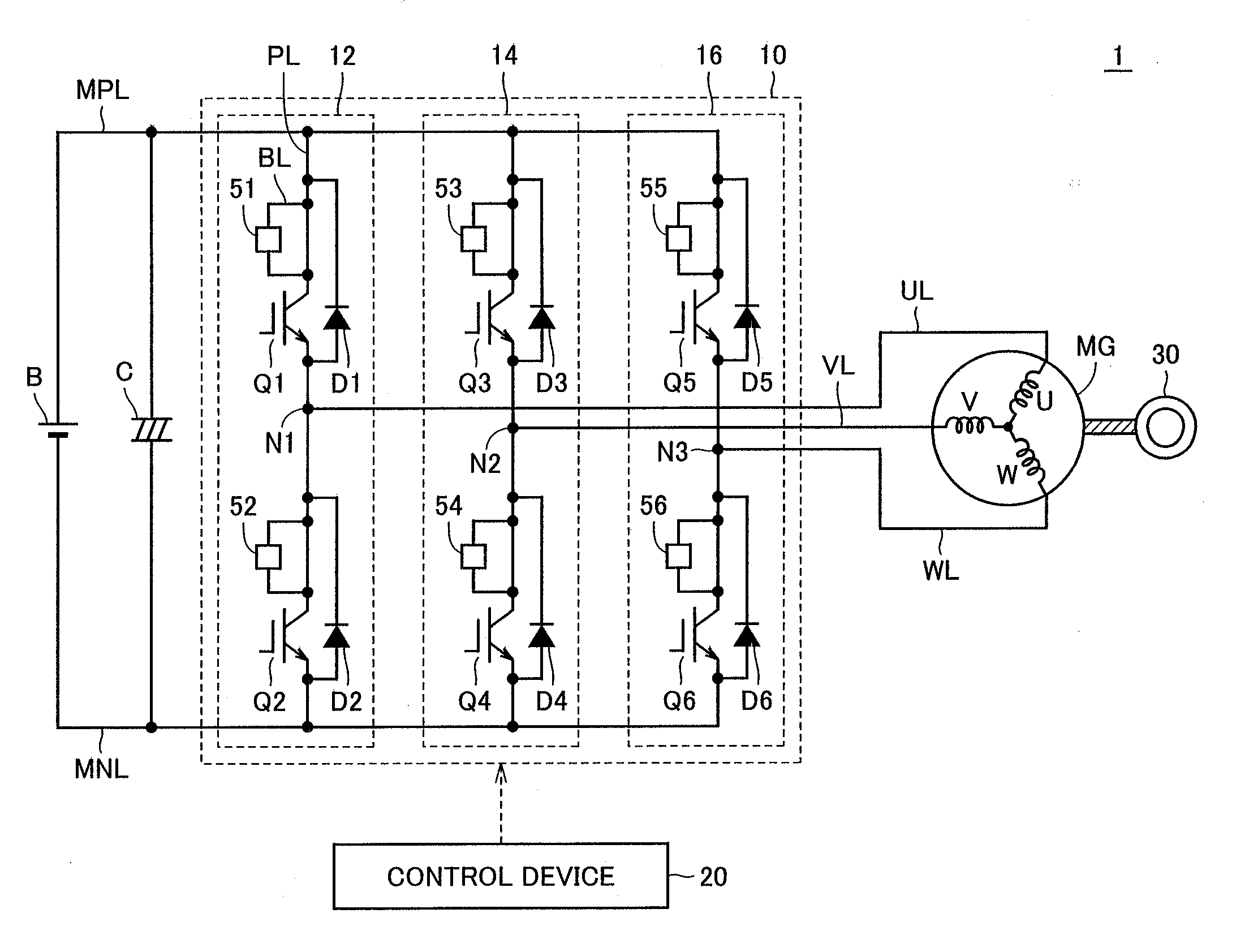
[0022]FIG. 1 shows a power train configuration of an electrically powered vehicle to which a semiconductor device according to a first embodiment of the present invention is applied. Referring to FIG. 1, electrically powered vehicle 1 includes a power storage device B, a capacitor C, an inverter 10, a motor generator MG, a wheel 30, and a control device 20.
[0023]Power storage device B has a positive electrode connected to a positive bus line MPL, and has a negative electrode connected to a negative bus line MNL. Capacitor C is connected between positive bus line MPL and negative bus line MNL. Inverter 10 includes a U-phase arm 12, a V-phase arm 14, and a W-phase arm 16. U-phase arm 12, V-phase arm 14, and W-phase arm 16 are connected in parallel between positive bus line MPL and negative bus line MNL.
[0024]U-phase arm 12 includes power transistors Q1, Q2, Peltier elements 51, 52, and diodes D1, D2. Power transistors Q1, Q2 are connected in series between positive bus line MPL and ne...
second embodiment
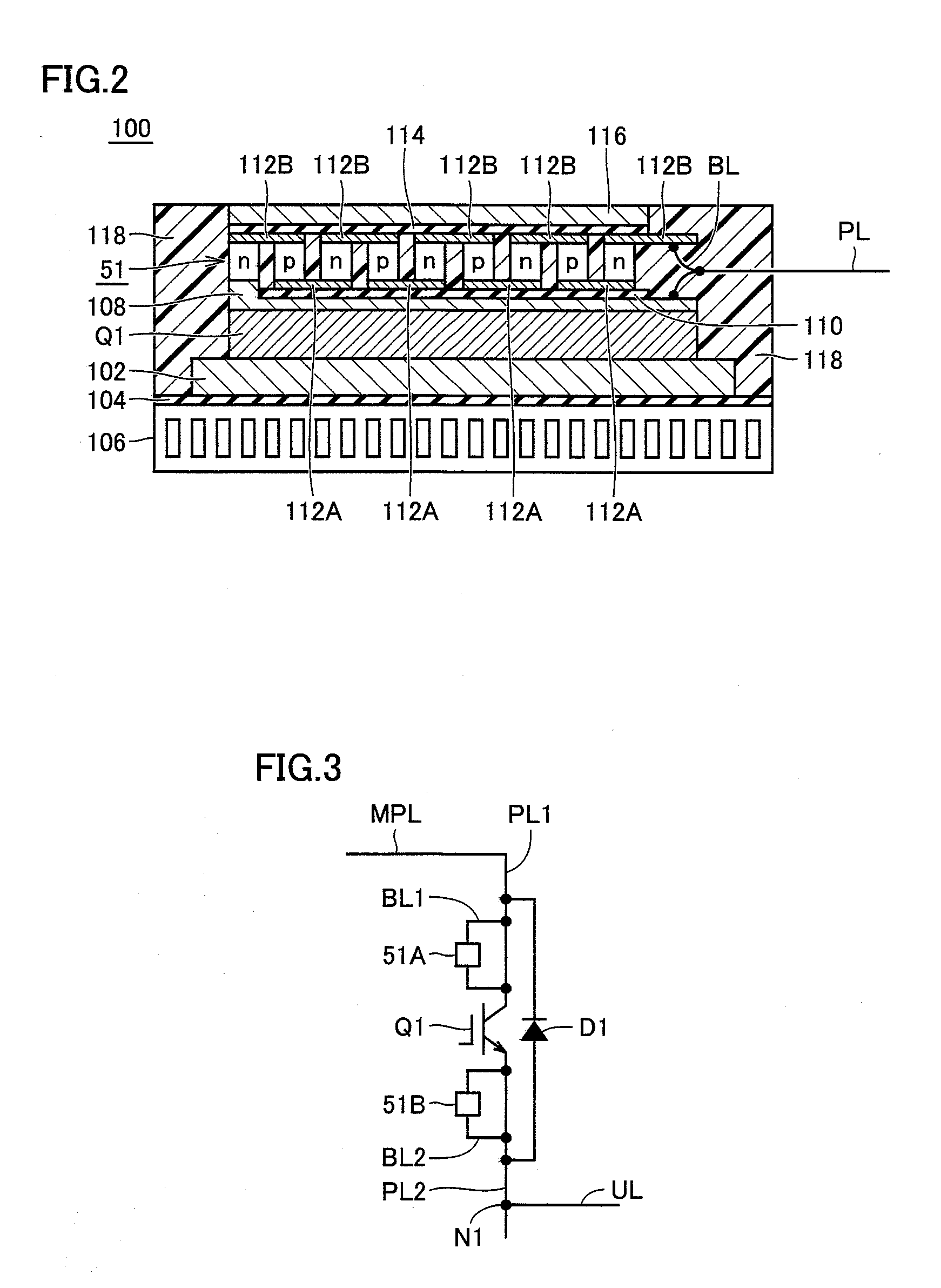
[0048]FIG. 3 is a circuit diagram of an upper arm of a U-phase arm of an inverter in a second embodiment. It should be noted that each of the other upper and lower arms has a configuration similar to that of the below-described upper arm of the U-phase arm.
[0049]Referring to FIG. 3, the upper arm of the U-phase arm includes a power transistor Q1, Peltier elements 51A, 51B, and a diode D1. Peltier element 51A is connected, in parallel, to a power line PL1 that connects the collector of power transistor Q1 to a positive bus line MPL. Peltier element 51B is connected, in parallel, to a power line PL2 that connects the emitter of power transistor Q1 to a node N1. Diode D1 is connected, in anti-parallel, to a circuit constituted by power transistor Q1 and Peltier elements 51A, 51B.
[0050]It should be noted that the other configurations of the electrically powered vehicle in the second embodiment are the same as those of electrically powered vehicle 1 of the first embodiment shown in FIG. ...
third embodiment
[0060]FIG. 5 is a circuit diagram of an upper arm of an U-phase arm of an inverter in a third embodiment. It should be noted that each of the other upper and lower arms has a configuration similar to that of the below-described upper arm of the U-phase arm.
[0061]Referring to FIG. 5, in the third embodiment, Peltier element 51 is connected, in parallel, to a power line that connects the emitter of a power transistor Q1 to a node N1. A diode D1 is connected, in anti-parallel, to a circuit constituted by power transistor Q1 and Peltier element 51.
[0062]It should be noted that the other configurations of an electrically powered vehicle in the third embodiment are the same as those of electrically powered vehicle 1 according to the first embodiment shown in FIG. 1.
[0063]According to the third embodiment, an advantage similar to that in the first embodiment can be obtained too.
PUM
 Abstract
Description
Claims
Application Information