
Spinel sintered body, production method thereof, transparent substrate, and liquid crystal projector

a technology of liquid crystal projector and spinel, which is applied in the direction of optics, instruments, optical elements, etc., can solve the problems of in-line transmittance decreasing, difficult to use this spinel sintered body in the visible region, and difficult to achieve the effect of stable transmittance, low heat absorption, and high light transmission characteristics

Inactive Publication Date: 2010-04-29
SUMITOMO ELECTRIC IND LTD
View PDF6 Cites 8 Cited by
  • Summary
  • Abstract
  • Description
  • Claims
  • Application Information

AI Technical Summary

Benefits of technology

[0015]It is possible to provide a sintered body having a spinel structure which has stable transmittance characteristics that are sufficient for use even in visible light. In addition, the spinel sintered body has high light transmission characteristics and can therefore control temperature rising of liquid crystal due to heat dissipation and low heat absorption caused by the light from the light source. Because of these characteristics, this spinel sintered body can be used as a transparent substrate for a liquid crystal projector.

Problems solved by technology

However, this spinel sintered body has a maximum in-line transmittance of 600-nm light of approximately 84% or less, and has a low in-line transmittance of light having a wavelength of 450 nm, and can therefore be used in the mid-infrared region but is difficult to use in the visible region, where high transmittance characteristics are required.
Because a spinel sintered body produced using this method exhibits a maximum in-line transmittance of 85% in the infrared region having a wavelength of 3 μm to 5 μm, but has an average in-line transmittance of 75% at wavelengths of 0.4 μm to 3 μm, it is also difficult to use this spinel sintered body in the visible region, where high light transmittance characteristics are required.
This transparent polycrystalline body has an average in-line transmittance of 84% for light having wavelengths in the range 400 μm to 800 μm, but the light transmittance of this spinel sintered body is variable and there are problems with the stability of the sintered body, such as the in-line transmittance being 80% or less depending on the sample measured.
In addition, if the thickness of the sintered body is 10 mm or more, a heterogeneous phase occurs in the central part of the sintered body, which results in the problem of the in-line transmittance decreasing.

Method used


Image

  • Spinel sintered body, production method thereof, transparent substrate, and liquid crystal projector
  • Spinel sintered body, production method thereof, transparent substrate, and liquid crystal projector
  • Spinel sintered body, production method thereof, transparent substrate, and liquid crystal projector

Examples


examples 1-7

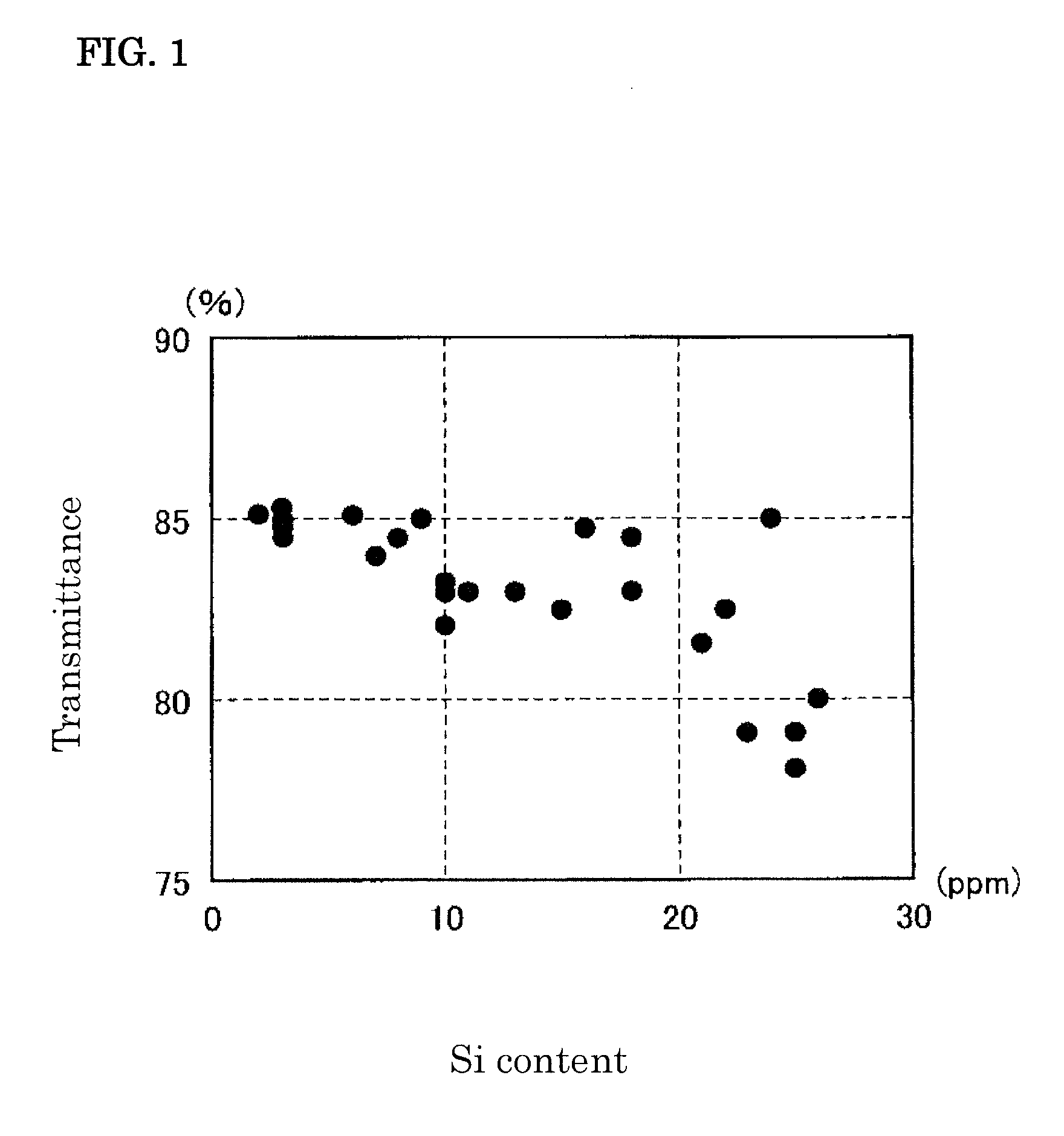
[0042]In these examples, the Si element content in the raw material spinel powders was varied to be 50 ppm or less, and the light transmittance of the spinel sintered bodies following forming was investigated. Firstly, spinel powders having purities of 99.5 mass % and containing impurities at the levels shown in table 1 were formed and then processed by CIP into bodies having a diameter of 95 mm and a length of 95 mm. Next, a first sintering step was carried out at 1600° C. in a vacuum at 20 Pa while heated at 1° C. / min. The densities of the obtained sintered bodies were 95% to 97%.

[0043]The minimum thickness D from the central part of the sintered body to the outer edge thereof was 39 mm, and because the heating conditions in the first sintering step were 1° C. / min, the time “t” required to reach the maximum temperature of 1600° C. from 1000° C. was 600 minutes. Therefore, because D=a×t1 / 2, “a” was calculated to be 1.6, which satisfies the relationship 1≦a≦3.

[0044]Next, a second si...

examples 8-10

,

Reference Example 1

[0046]In these examples, the heating time “t” in the first sintering step was varied (D was fixed), and the relationship between the value of a, calculated from the relationship D=a×t1 / 2, and the Si element content and the light transmission characteristics of the sintered body was investigated.

[0047]Using the spinel powder used in Example 5, the value of a was altered as shown in table 2 by altering the heating time (t) without altering D in the first sintering step, and spinel sintered bodies were produced in the same way as in Example 5 in terms of other conditions. The measurements were carried out in the same way as in Example 5, with the Si element content of the sintered body formed in the first sintering step and the in-line transmittance of the sintered body following completion of the second sintering step being measured. The measurement results are shown in table 2.

TABLE 2Si elementIn-line transmittance (%)contentWavelengthWavelengtha(ppm)350 nm450 nmR...


PUM

PropertyMeasurementUnit
Temperatureaaaaaaaaaa

Abstract

A spinel sintered body has a composition of MgO·nAl2O3 (1.05≦n≦1.30) containing 20 ppm or less of Si element. A production method thereof includes the steps of: forming a compacted body from a spinel powder containing 50 ppm or less of Si element and having a purity of not less than 99.5 mass %; a first sintering step of forming a sintered body having a density of not less than 95% by sintering the compacted body at 1500° C. to 1700° C. in a vacuum; and a second sintering step of subjecting the sintered body to pressurized sintering at 1600° C. to 1800° C.

Description

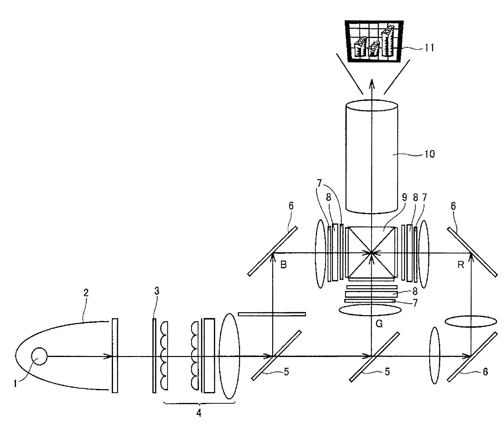
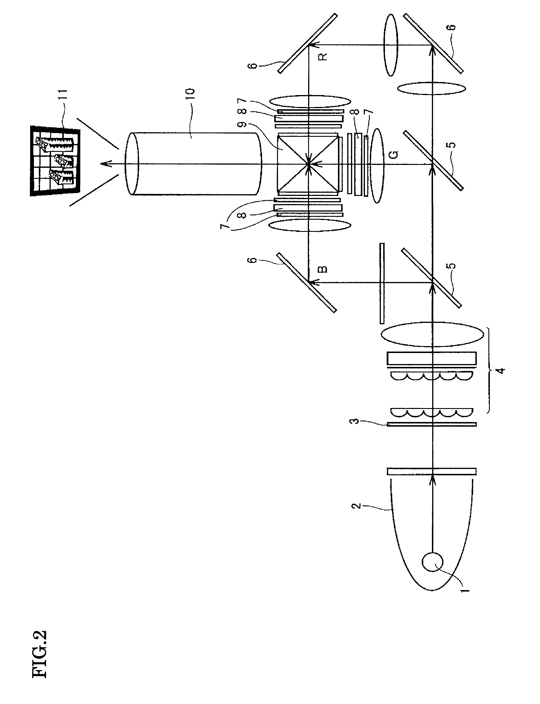
TECHNICAL FIELD [0001]The present invention relates to a spinel sintered body having excellent transparency and stability of transparency, and a method for producing this spinel sintered body. In addition, the present invention also relates to a transparent substrate comprising this spinel sintered body, and a liquid crystal projector provided with this transparent substrate.BACKGROUND ART [0002]Spinel sintered bodies are cubic crystals having a crystal form which does not possess polarization properties, have relatively high thermal conductivity among oxide ceramics, and exhibit transparency in the mid-infrared region to visible region, and are therefore of interest as polarizing plates in a variety of electronic devices, such as liquid crystal projectors or rear-projection televisions, as light-transmitting windows such as dust-proofing windows, or as transparent substrate materials for lenses and the like.[0003]FIG. 2 shows a typical structure of a liquid crystal projector. As sh...

Claims


Application Information

Patent Timeline
IPC IPC(8): G02F1/1333C04B35/053
CPCC04B35/443C04B35/6455C04B41/009G03B21/00G02F2203/06G02F2203/01G02F2202/09G02F2201/50G02F2001/133311C04B41/52C04B41/89C04B2111/805C04B2235/3201C04B2235/3208C04B2235/3272C04B2235/3418C04B2235/6581C04B2235/661C04B2235/72C04B2235/77C04B2235/79C04B2235/9653G02B1/02C04B41/4529C04B41/5027C04B41/5055G03B21/005G02F1/133311
Inventor YOSHIMURA, MASASHIYOSHIKANE, TAKENORINAKAYAMA, SHIGERUFUJII, AKIHITO
Owner SUMITOMO ELECTRIC IND LTD
Learn More