
Pinned Lock Joint

a technology of pin lock and pin joint, which is applied in the direction of rod connection, pipe, fastening means, etc., can solve the problems of assembling components, failure of joints, cost of product shipping to the end user,

Inactive Publication Date: 2010-04-29
SPALDING LAMAR
View PDF23 Cites 33 Cited by
  • Summary
  • Abstract
  • Description
  • Claims
  • Application Information

AI Technical Summary

Benefits of technology

[0017]A method for joining two rigid members at an angle to each other comprised of a profile on the male member which closely mates with a corresponding hole or open ended slot in the female member. After assembly the male and female components are assembled, a pin is inserted through both components approximately perpendicular to the axis of assembly. Socking the two members together. The novelty in this invention is that its method for joining the two members reduces material usage and complexity of manufacture without sacrificing strength of the joint.

Problems solved by technology

The long length can lead to very highly leveraged loads at the joint holding the top to the leg, leading to joint failure.
The durability and cost to deliver a product using any given joint design depends upon (1) the quantity of material used, (2) the type and quality of materials used, (3) the difficulty to manufacture the components, (4) the difficulty to assemble the components, and (5) the cost to ship the product to the end user.
Prior to the present invention, methods for directly joining the legs to the top have resulted in weak joints prone to failure when typical leveraged loads are applied to the legs.
These connectors are most commonly glued and / or screwed to the table top, and lit to the legs, resulting in a weak, joint.
A drawback to the use of a frame instead of directly joining the legs to the top is that it is more expensive.
This is weak and fails quickly under relatively low loads.
To add support, braces and mechanical fasteners such as bolts and screws can then be added increasing manufacturing costs.
While these joints significantly improve the strength of the joints, they are far more difficult to manufacture and assemble with the precision required to assure the required strength.
The general result of these limitations is that inexpensive mass produced furniture uses relatively inexpensive materials and joinery techniques leading to relatively short life before failure under load.
Eliminating the frame reduces the quantity of material required and the consequent costs (1) to store the materials, (2) of scrap loss incurred through waste and defects, (3) of product weight, and hence transportation costs.
Should there be any error in machining the components will not fit together well and the joint will be weakened.
This significantly reduces the structural requirements and the attendant manufacturing costs for the pin and its attachment.

Method used


Image

  • Pinned Lock Joint
  • Pinned Lock Joint
  • Pinned Lock Joint

Examples


Embodiment Construction

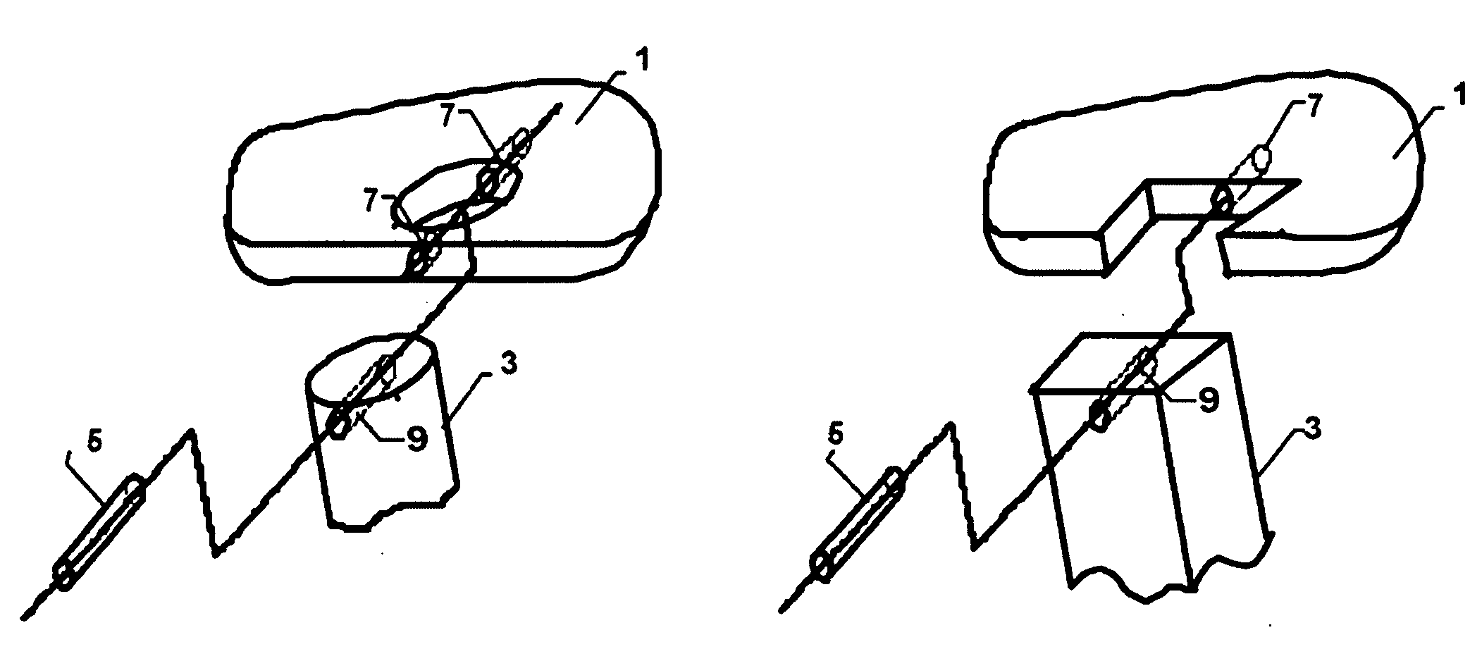
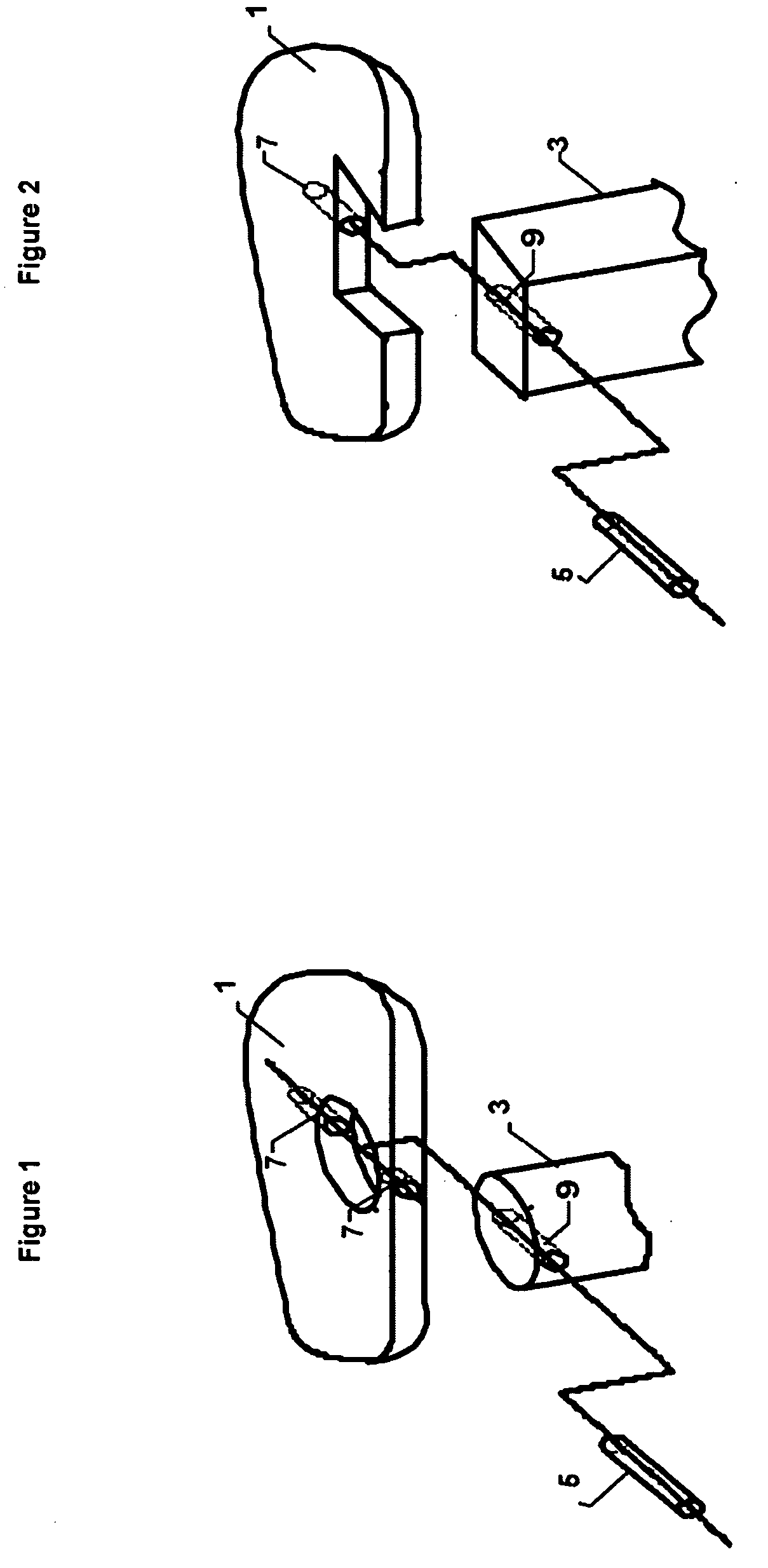
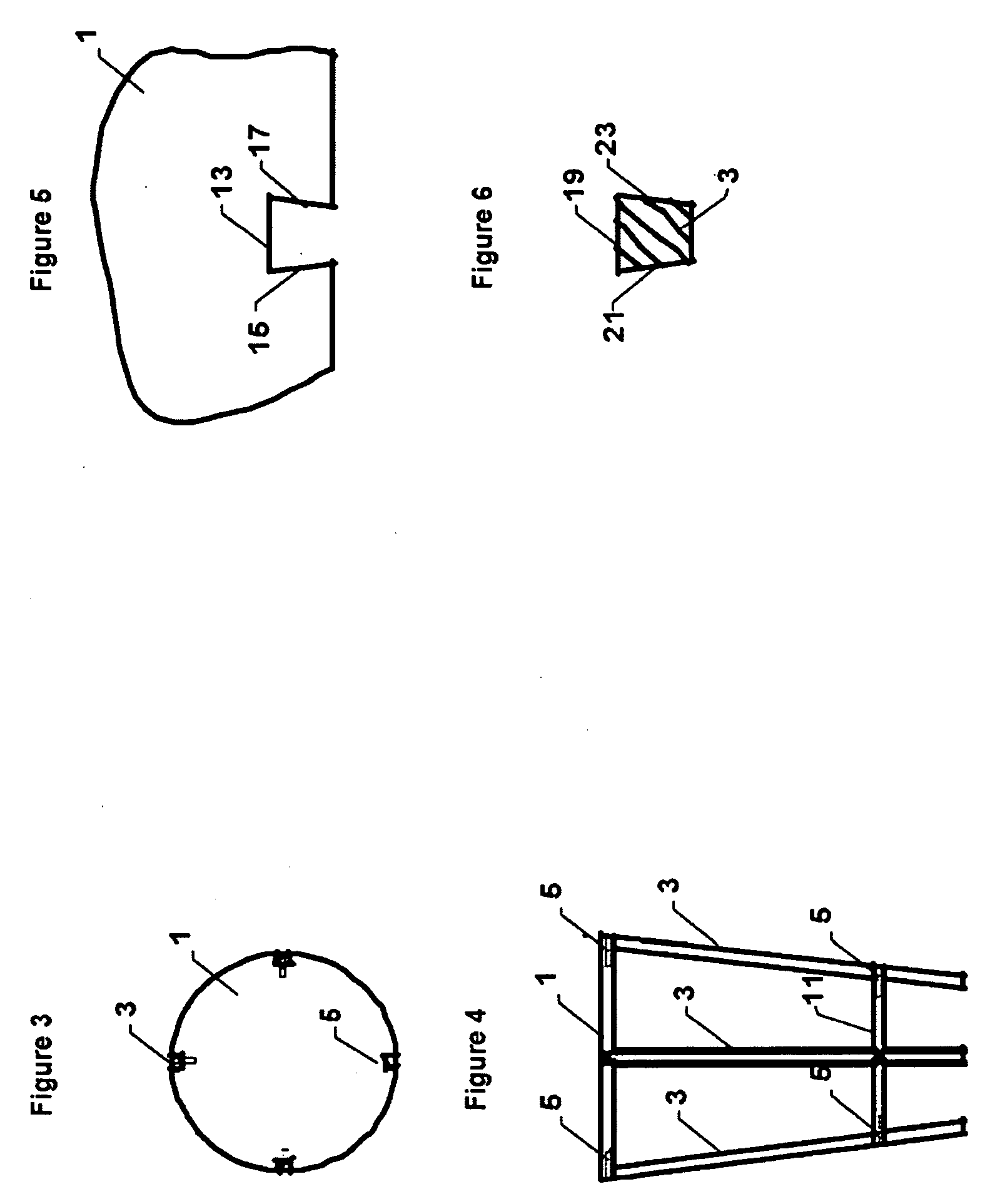
[0018]One embodiment of the joint is shown in FIGS. 1, through 5 wherein the joint is used in eight places to connect four table legs to a table top and a table shelf. Each joint in made up of 3 members, the top (1), or shelf (7), the leg (3), and the pin (5), Each individual member is constructed to mate with the other two members in an intimate manner.

[0019]In this embodiment the top member is made from wood and is 24 inches in diameter, and ¾ inches in diameter, although neither of these features is essential to the implementation of this design. The top only needs have features large enough to completely surround the mating leg (FIG. 2), be amenable to precision forming or machining, and be of sufficient strength for the anticipated application. Into the top and at an angle of 10 degrees (9) to the face of the top 4 dovetail slots (FIG. 2 and FIG. 5) are machined immediately adjacent to edge and through the top at 90 degree intervals around the top. The 10 degree angle (9) is on...


PUM


Abstract

The Pinned Lock Joint is an improved method for joining two members together such as between a table leg and table top. A portion of the male member (the leg) is formed to completely and intimately fit into a hole or open ended slot in the female member (the top). The hole or open ended slot milled into and or through the female member is configured such that the male member can only be inserted into it along one axis of assembly, preventing disassembly along any other axis of motion. After the two members are assembled, a pin is inserted into and through both members approximately perpendicular to the axis of assembly, preventing disassembly along the original axis of assembly, and thus locking the two members together.

Description

BACKGROUND OF THE INVENTION[0001]This invention relates generally to the structural joining of two separate rigid members such as might be found in an article of furniture, although it is applicable to many other constructions as well. When it is not possible to weld the two pieces together, there are a number of methods for forming the interface between two members to assist in joining them together securely. These are used in conjunction with fasteners and adhesives to either permanently or detachably join the two members. Of particular relevance to this invention are the prior methods of mechanically joining the members. The prior art includes the finger joint in which one or more machined pins with parallel sides are fit into mating open ended slots preventing disassembly in one direction only. A modification of this joint is the mortise and tenon joint having a machined pin or tenon similar to the finger joint pin, but which is mated into a hole or mortise as opposed to a open ...

Claims


Application Information

Patent Timeline
IPC IPC(8): F16B12/24
CPCA47B13/021Y10T403/3913F16B12/28F16B9/02
Inventor SPALDING, LAMAR
Owner SPALDING LAMAR
Learn More