
Laminated plate and manufacturing method thereof

a technology of laminated plates and manufacturing methods, applied in the field of laminated plates, can solve the problems of weak strength cumbersome work, distortion of vehicle interior panels,

Active Publication Date: 2010-04-29
MEIWA IND CO LTD
View PDF6 Cites 17 Cited by
  • Summary
  • Abstract
  • Description
  • Claims
  • Application Information

AI Technical Summary

Benefits of technology

[0011]An invention according to claim 6 is a laminated plate, in which a height-increasing bridge member is interposed between two plate portions made of thermoplastic resin, and end portions of the two plate portions are welded to each other, characterized in that used as the height-increasing bridge member is at least one of a thermoplastic resin-foamed molded body, a molded body obtained by laminating a synthetic resin sheet or a synthetic resin foamed sheet between two upper and lower metal plates, an embossed shaped molded body having longitudinal wall portions, a honeycomb structure molded body having longitudinal wall portions, in which air holes are formed in the longitudinal wall portions, a grid-like structure molded body having longitudinal wall portions, in which air holes are formed in the longitudinal wall portions, a chip urethane resin molded body, a chip felt molded body, and a corrugated cardboard molded body.
[0006]In this connection, it is an object of the present invention to obtain a laminated plate capable of enhancing strength thereof and capable of suppressing the occurrence of the distortion after the laminated plate is molded regardless of a size thereof, and to obtain a manufacturing method of the laminated plate.

Problems solved by technology

However, in such a conventional technology, an inside of the vehicle interior panel is hollow, and there has been a problem that strength of the vehicle interior panel is weak.
However, in the above-described conventional technology, since the bridge member cannot be inserted in advance into the inside of the vehicle interior panel, it is necessary to do work of notching a part of the vehicle interior panel after the vehicle interior panel is molded, inserting the bridge member into the inside of the vehicle interior panel, and thereafter closing such a notched portion again.
This work has been cumbersome.
Moreover, in the above-described conventional technology, the vehicle interior panel is molded only by clamping the metal dies together and being blow-molded, and accordingly, a shape cannot be imparted to the vehicle interior panel so that the vehicle interior panel can go along inner surface shapes of the metal dies, and it has been apprehended that distortion may occur on a surface of a panel base material of the vehicle interior panel.
Furthermore, in the above-described conventional technology, an upper portion of the parison is pulled and extended owing to self weight of the parison as the parison is being suspended.
Accordingly, there have been problems that upper and lower portions of the panel base material differ from each other in thickness, resulting in a strength difference of the panel among portions thereof, and in an occurrence of the distortion caused by the fact that the vehicle interior panel is cooled after being molded and that a temperature is changed during use of the panel concerned.
Accordingly, it can be said that such a method of suspending the parison and performing the blow molding for the hollow panel is not very suitable for the molding of a large-size panel.

Method used


Image

  • Laminated plate and manufacturing method thereof
  • Laminated plate and manufacturing method thereof
  • Laminated plate and manufacturing method thereof

Examples


first modification example

[0067]FIG. 6 is a plan view showing a state where grid-like structure molded bodies and the reinforcements are arranged on the back surface side sheet material according to a first modification example of this embodiment, FIG. 7 is a perspective view of the grid-like structure molded body according to the first modification example, and FIG. 8 is a cross-sectional view of a vehicle deck board according to the first modification example. Note that this modification example includes similar constituents to those of the above-mentioned first embodiment. Hence, common reference numerals are assigned to these similar constituents, and a duplicate description will be omitted.

[0068]In the vehicle deck board 1A according to this modification example, instead of the foamed resins 13 of the above-mentioned embodiment, grid-like structure molded bodies 27 having longitudinal wall portions 27a as shown in FIG. 7 are used as the height-increasing bridge members. Each of these grid-like structure...

second modification example

[0076]FIG. 9 is a plan view showing a state where honeycomb structure molded bodies and the reinforcements are arranged on the back surface side sheet material according to a second modification example of this embodiment, FIG. 10 is a perspective view of the honeycomb structure molded body according to the second modification example, and FIG. 11 is a cross-sectional view of a vehicle deck board according to the second modification example. Note that this modification example includes similar constituents to those of the above-mentioned first embodiment. Hence, common reference numerals are assigned to these similar constituents, and a duplicate description will be omitted.

[0077]In the vehicle deck board 1B according to this modification example, instead of the foamed resins 13 of the above-mentioned embodiment, hexagonal honeycomb structure molded bodies 28 having longitudinal wall portions 28A as shown in FIG. 10 are used as the height-increasing bridge members. Each of these hon...

third modification example

[0082]FIG. 12 is a plan view showing a state where embossed shaped molded bodies and the reinforcements are arranged on the back surface side sheet material according to a third modification example of this embodiment, FIG. 13 is a perspective view of the embossed shaped molded body according to the third modification example, and FIG. 14 is a cross-sectional view of a vehicle deck board according to the third modification example. Note that this modification example includes similar constituents to those of the above-mentioned first embodiment. Hence, common reference numerals are assigned to these similar constituents, and a duplicate description will be omitted.

[0083]In the vehicle deck board 1C according to this modification example, instead of the foamed resins 13 of the above-mentioned embodiment, embossed shaped molded bodies 29 having longitudinal wall portions 29a as shown in FIG. 13, that is, embossed shaped molded bodies 29 uneven in cross section, which have columnar emb...


PUM

PropertyMeasurementUnit
Lengthaaaaaaaaaa

Abstract

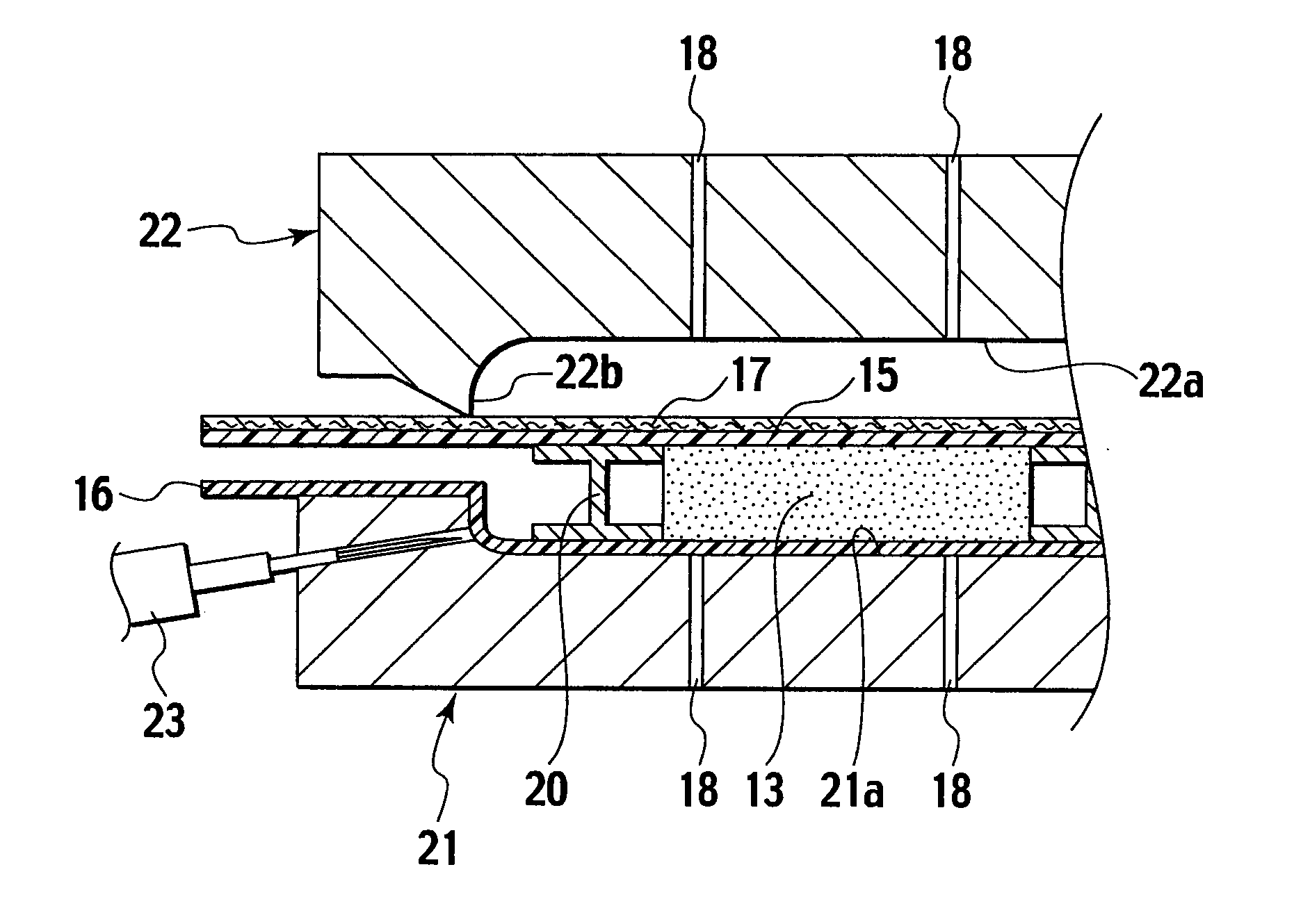
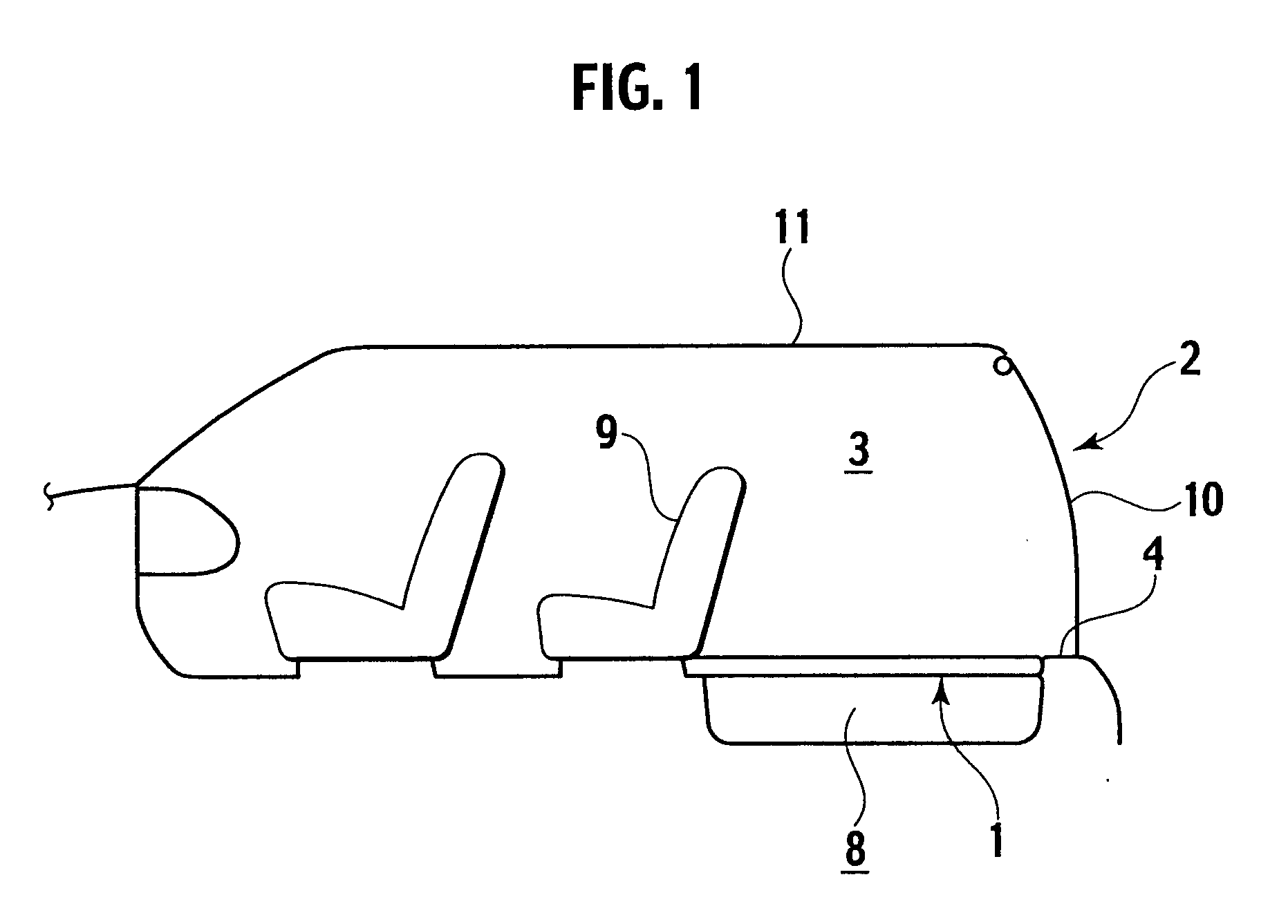
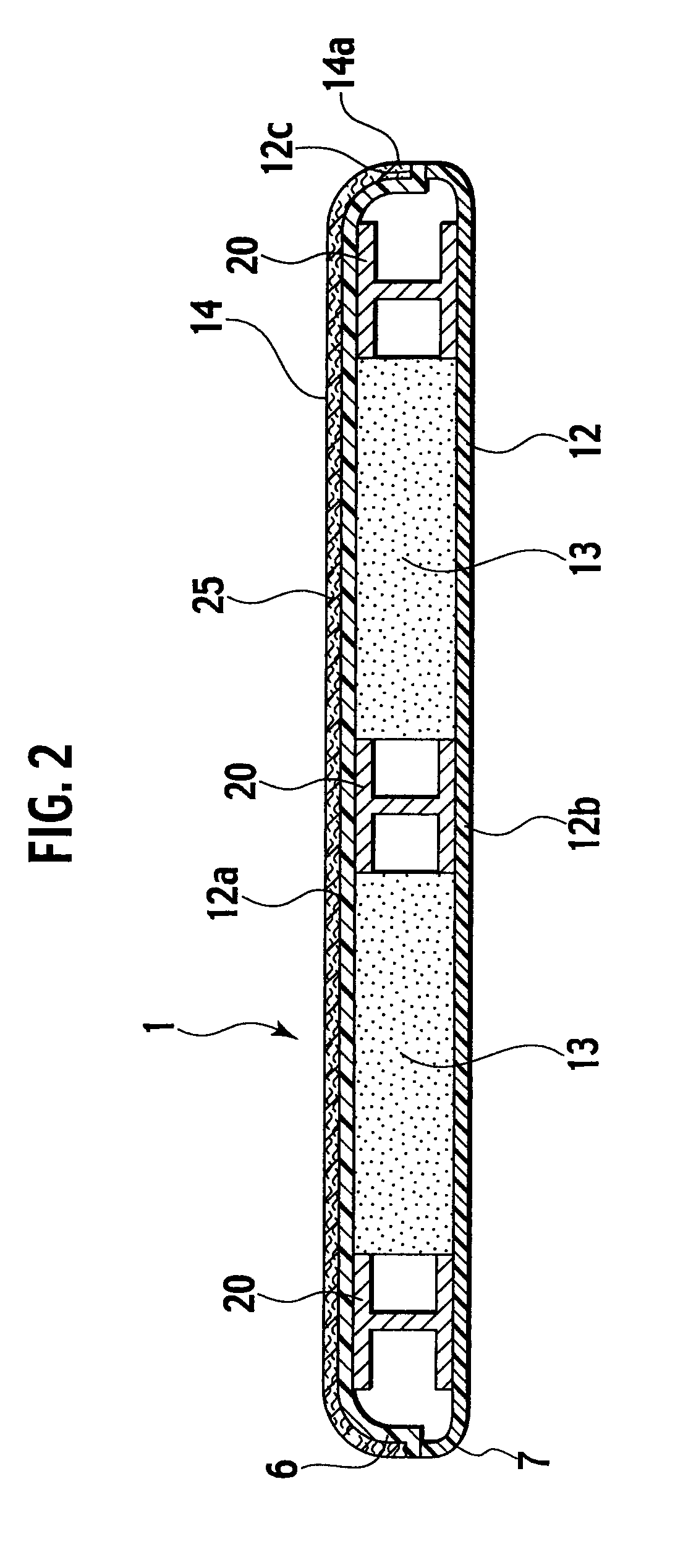
A vehicle deck board 1 is molded in such a manner that a lower die 21 and an upper die 22 are clamped together in a state where foamed resins 13 and reinforcements 20 are interposed between a back surface side sheet material 16 and a front surface side sheet material 15, whereby the back surface side sheet material 16 and the front surface side sheet material 15 are welded to each other to thereby form a laminated member 26 with height-increasing bridge members included therein, compressed air is injected into an inside of the laminated member 26 with the height-increasing bridge members included therein, which is formed by welding the back surface side sheet material 16 and the front surface side sheet 15, while individually vacuum-sucking the back surface side sheet material 16 and the front surface side sheet material 15 to the lower die 21 and the upper die 22, and the laminated member 26 concerned is subjected to blow molding.

Description

TECHNICAL FIELD[0001]The present invention relates to a laminated plate and a manufacturing method thereof.BACKGROUND ART[0002]Heretofore, as disclosed in Japanese Patent Laid-Open Publication No. 2006-182208, a vehicle interior panel and a molding method thereof have been known as a laminated plate and a manufacturing method thereof. In the molding method, a parison made of a thermoplastic is extruded from an extrusion head, the parison concerned is suspended between one of metal dies and the other metal die, a skin sheet is arranged between the parison and the one metal die, the metal dies are clamped together, and a pressurized fluid is introduced into the parison to perform blow molding for the parison.[0003]However, in such a conventional technology, an inside of the vehicle interior panel is hollow, and there has been a problem that strength of the vehicle interior panel is weak. Accordingly, it is necessary to enhance the strength of the vehicle interior panel by inserting a ...

Claims


Application Information

Patent Timeline
IPC IPC(8): B32B1/06B28B23/22
CPCB29C49/0047Y10T428/233B29C51/10B29C51/12B29C51/14B29C51/32B29C2049/2008B29C2049/2013B29C2049/2065B29C2791/001B29C2791/006B29C2791/007B29D99/001B29K2023/12B29K2105/0809B29K2105/16B29L2009/00B29L2031/3017B29L2031/608B60R5/04B32B3/02B32B3/12B32B5/18Y10T428/239Y10T428/24661Y10T428/24628Y10T428/19Y10T156/1025Y10T428/236Y10T428/1372B29C49/20Y10T428/249953Y10T428/249991Y10T428/249992B29C49/0691B29C49/42B32B3/26B32B15/08
Inventor KITANO, SENKIUCHI, HIROYUKIYUZAWA, ICHIRONOZAWA, KOHSEI
Owner MEIWA IND CO LTD
Learn More