
Matching method of pattern layouts from inverse lithography

Active Publication Date: 2010-04-29
NAN YA TECH
View PDF7 Cites 2 Cited by
  • Summary
  • Abstract
  • Description
  • Claims
  • Application Information

AI Technical Summary

Benefits of technology

[0009]The object of the present invention is to provide a matching method for layout patterns, which makes all patterns in a group identical through categorizing patterns into groups, inspecting the processed patterns and replacing variant processed patterns by a selected one. The purpose of the method is to settle the existing problem that unexpectedly different photomask patterns are produced from the same design layout pattern in the same condition. Then, time will be saved for not verifying the photomask layout several times and the yield will increase.

Problems solved by technology

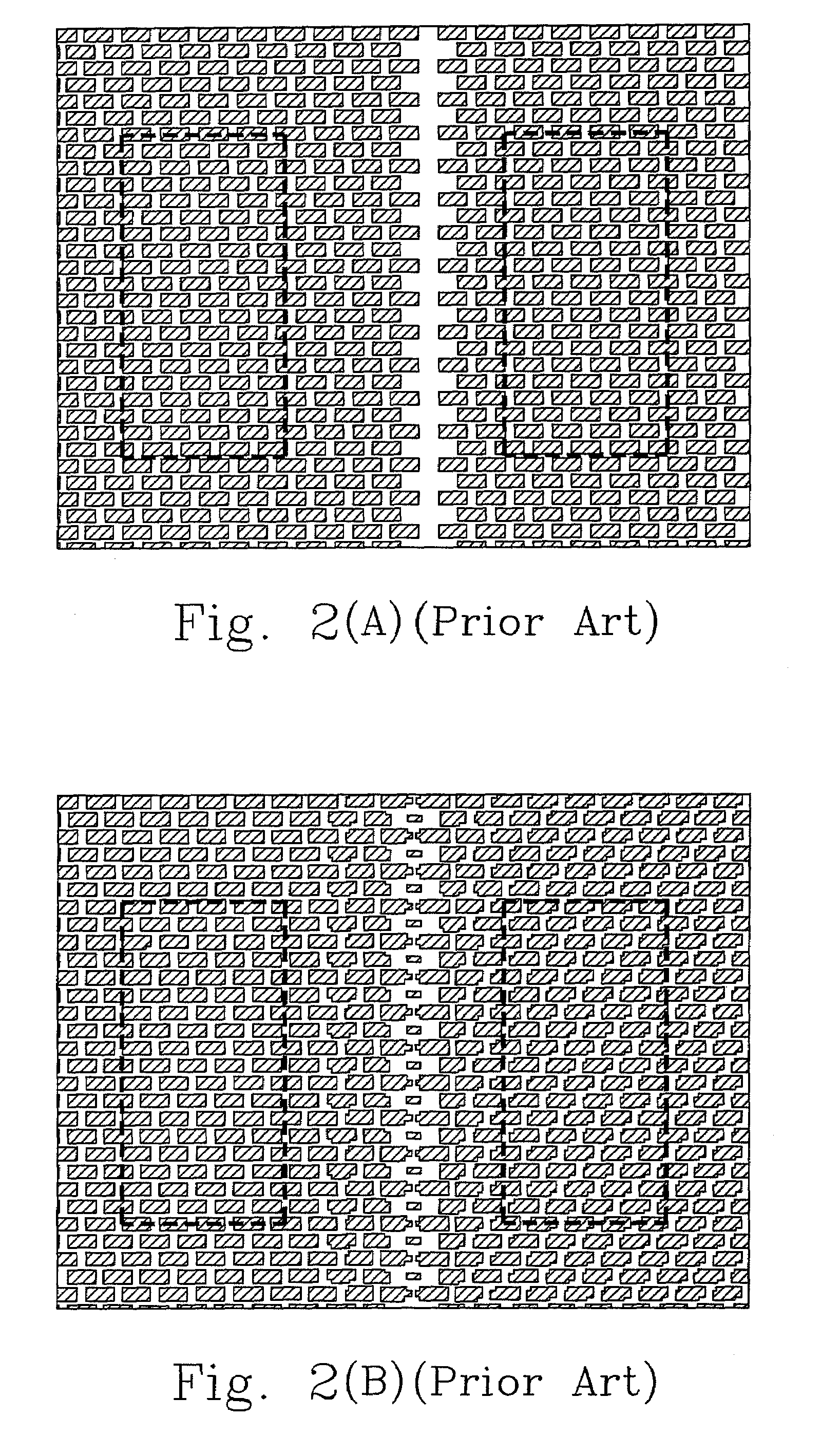
In the above prior flow, there is usually an existing problem that the unexpectedly different photomask patterns as FIG. 2(B) are produced even in the same design layout condition as FIG. 2(A).
It may take much time for verifying the photomask layout once we have doubts about the photomask layout.
In addition, using the wrong photomask may cause the yield to decrease.

Method used


Image

  • Matching method of pattern layouts from inverse lithography
  • Matching method of pattern layouts from inverse lithography
  • Matching method of pattern layouts from inverse lithography

Examples


Embodiment Construction

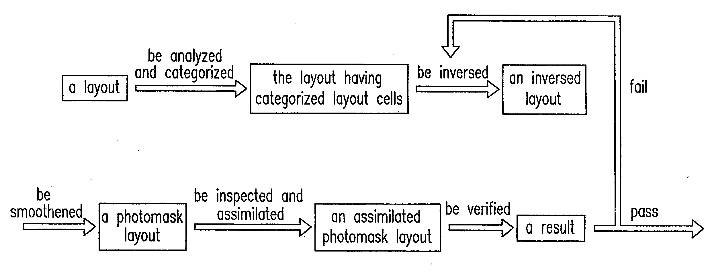
[0044]Please refer to FIG. 3, which shows a flow chart of the first preferable embodiment to make photomask layout cells in the group identical for shape and size. The method is usually executed by a prior computer program as follows.

[0045]Firstly, provide a layout having a plurality of initial layout cells which may be different (shape or size) or the same (shape and size). Please refer to FIG. 4, which shows a layout.

[0046]Then, analyze the layout by a method, especially a hierarchical method to obtain a hierarchical structure having the plurality of initial layout cells. The purpose of using the hierarchical method is to categorize ones of the plurality of initial layout cells having (or consisting of) a specific pattern into a group. In FIG. 4, the initial layout cells 401 and 402 have the same patterns. In order to make the layout and the photomask layout be inspected conveniently and match with each other, ones of the plurality of initial layout cells having (or consisting of)...


PUM


Abstract

The present invention relates to a matching method of pattern layouts from inverse lithography, which makes the pattern cells in the same groups identical to avoid a repeated verification and to improve the yield. The method comprises the step of: analyzing a target designed layout by hierarchy; categorizing the pattern cells with the same shape into a group; inversing the target designed layout by inverse lithography; inspecting the inversed pattern cells in the group with each other and replacing the variant ones to make all the inversed pattern cells identical.

Description

FIELD OF THE INVENTION[0001]The present invention generally relates to a matching method of pattern layouts from inverse lithography. In particular, the matching method comprises the step of: analyzing a design layout by hierarchy; categorizing the cells with the same pattern into a group; inversing the design layout by inverse lithography; assimilating the inversed layout cells in the same group into a selected inversed layout cell.BACKGROUND OF THE INVENTION[0002]Nowadays the most of integrated circuits (ICs) are created by designers using computer programs. Designers define the functionalities of the circuit and analyze them by using computer programs to obtain the electronic equivalent of a circuit diagram.[0003]In order to convert the circuit diagram into a physical integrated circuit, a place and route tool is needed to arrange every electronic component and to construct the wiring to interconnect them for a design layout. Besides, the layers of the layout are to be fabricated...

Claims


Application Information

Patent Timeline
IPC IPC(8): G03F1/00
CPCG03F1/36G03F1/144
Inventor FU, KUO-KUEI
Owner NAN YA TECH
Learn More