
Method and apparatus for producing toner

Inactive Publication Date: 2010-04-29
RICOH KK
View PDF12 Cites 21 Cited by
  • Summary
  • Abstract
  • Description
  • Claims
  • Application Information

AI Technical Summary

Benefits of technology

[0009]Accordingly, exemplary embodiments of the present invention provide a method and an apparatus for producing toner which can produce a toner having a narrow size distribution with high productivity.

Problems solved by technology

However, pulverization methods have a disadvantage that the resulting toner particles have a wide variety of shape and size.
If dispersing agents remain on the surface of the resultant toner, chargeability and environmental stability of the toner may deteriorate.
In order to remove remaining dispersing agents, disadvantageously, an extremely large amount of washing water is needed.
Spray drying methods also have a disadvantage that the resulting toner particles have a wide variety of shape and size.
This toner production apparatus has a disadvantage that the resultant particles have a wide size distribution, which may result in poor toner productivity.

Method used


Image

  • Method and apparatus for producing toner
  • Method and apparatus for producing toner
  • Method and apparatus for producing toner

Examples


example 1

(Preparation of Mother Particles)

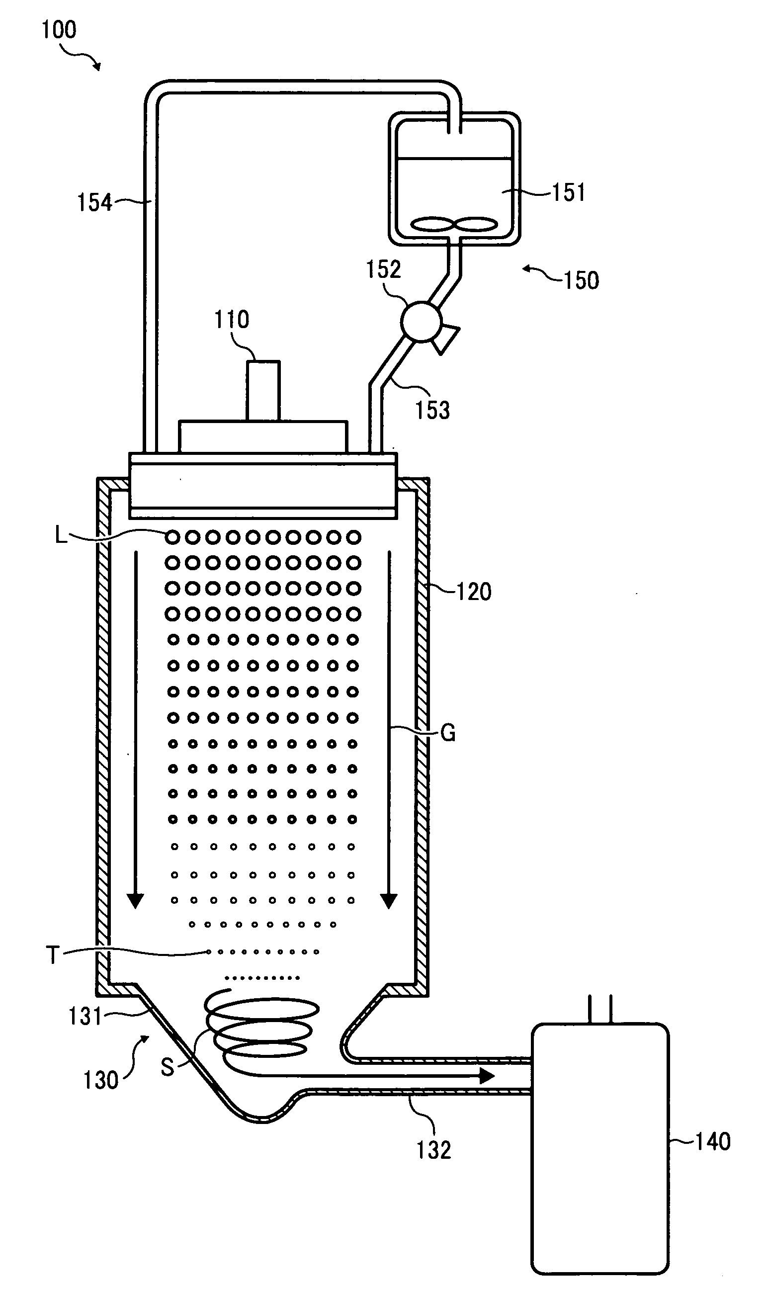
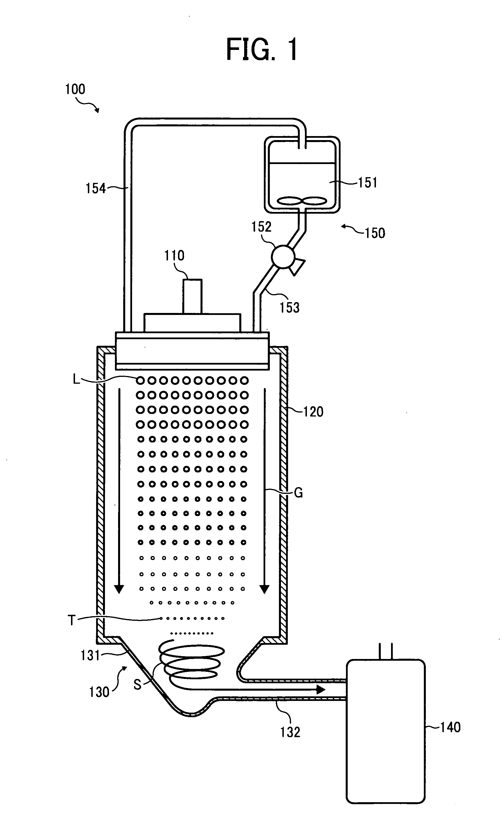
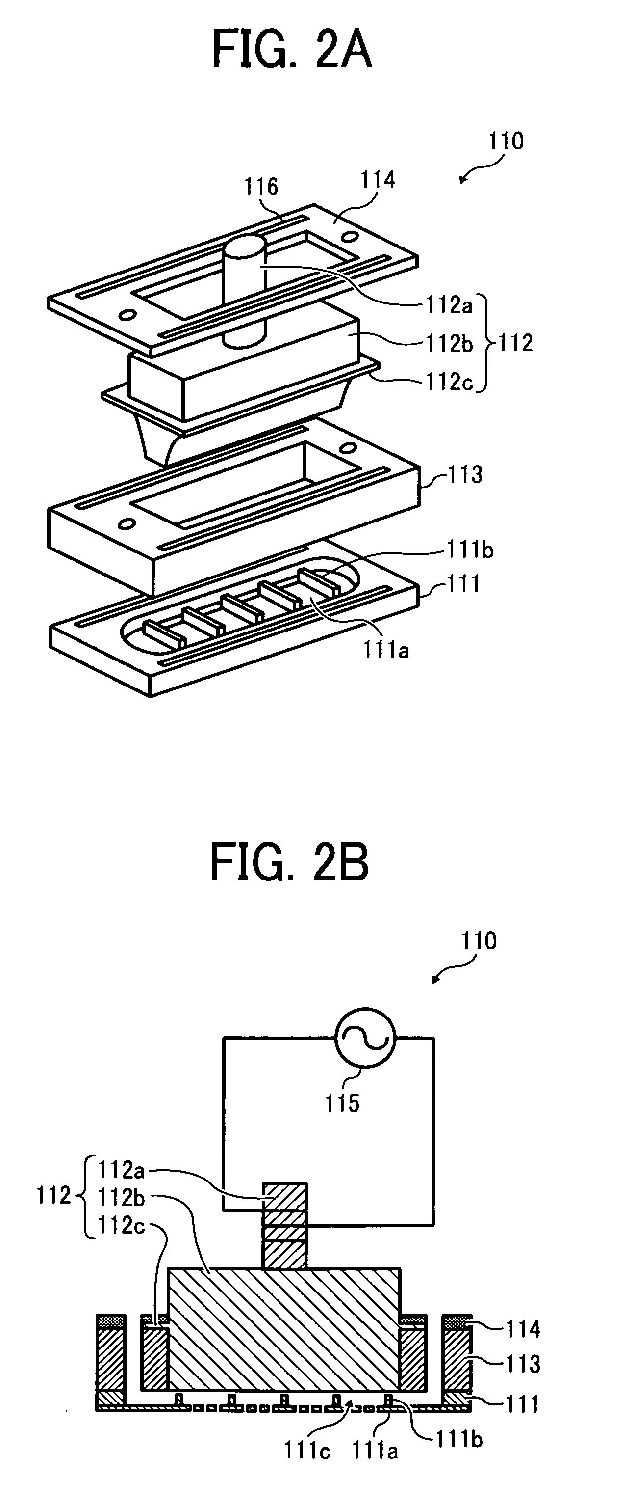
[0136]The toner components liquid was contained in the tank 151 and supplied to the liquid droplet discharge unit 110 using the pump 152 in the toner production apparatus 100 illustrated in FIG. 1. The thin film 111a was made from an SOI substrate having a thickness of 500 μm, by the method illustrated in FIGS. 3A to 3D. The openings 211a and 213a were formed into hound's-tooth pattern in which the distance between adjacent openings 213a was 100 μm. The openings 211a and 213a each had a diameter of 100 μm and 8.5 μm, respectively. The thin film 111a had a resonance frequency of 74 kHZ when measured using PSV300 (from Polytech). The thin film 111a was bonded to the retention member 111 so that the openings 211a face the retention regions 111c and the openings 213a discharge the toner components liquid. The number of the retention regions 111c formed by the partitions 111b within the retention member 111 was 6. Each of the retention regions 111c had 48...

example 2

[0140]The procedure for preparing toner in Example 1 is repeated except that the retention member 111 is replaced with another one in which 6,400 discharge openings are formed in a reticular pattern in each of the retention regions 111c. The thin film 111a has a resonance frequency of 74 kHZ when measured using PSV300 (from Polytech). The toner production apparatus 100 is brought into operation for 1 hour and 320 g of mother particles T are obtained. The mother particles T stored in the storage part 140 are subjected to a measurement of particle size distribution using a particle size analyzer FPIA-2000 (from Sysmex Corporation). As a result, the mother particles T have a weight average particle diameter of 5.4 μm and a number average particle diameter of 5.2 μm.

example 3

[0141]The procedure for preparing toner in Example 1 is repeated except that the retention member 111 is replaced with another one in which 7,390 discharge openings are formed in each of the retention regions 111c. The thin film 111a has a resonance frequency of 74 kHZ when measured using PSV300 (from Polytech). The toner production apparatus 100 is brought into operation for 1 hour and 382 g of mother particles T are obtained. The mother particles T stored in the storage part 140 are subjected to a measurement of particle size distribution using a particle size analyzer FPIA-2000 (from Sysmex Corporation). As a result, the mother particles T have a weight average particle diameter of 5.4 μm and a number average particle diameter of 5.2 μm.


PUM

PropertyMeasurementUnit
Diameteraaaaaaaaaa
Particle sizeaaaaaaaaaa
Frequencyaaaaaaaaaa

Abstract

A method and an apparatus for producing toner are provided. A fluid comprising a resin and a colorant is supplied to a retention member that includes a film on which multiple discharge openings are formed. The fluid which is supplied to the retention member is resonated so that liquid droplets thereof are discharged from the multiple openings. The liquid droplets which are discharged from the multiple openings are solidified to form mother particles of a toner.

Description

BACKGROUND OF THE INVENTION[0001]1. Field of the Invention[0002]The present invention relates to a method and an apparatus for producing toner.[0003]2. Discussion of the Related Art[0004]In image forming processes such as electrophotography, electrostatic recording, and electrostatic printing, electrostatic latent images are generally developed with developers. More specifically, a developer is adhered to an electrostatic latent image that is formed on an electrostatic latent image bearing member. Subsequently, the developer is transferred from the electrostatic latent image bearing member onto a transfer medium and fixed thereon. Developers are broadly classified into two-component developers comprising a carrier and a toner and one-component developers comprising no carrier and a toner (e.g., a magnetic toner, a non-magnetic toner).[0005]Toners may be produced by what is called pulverization methods. However, pulverization methods have a disadvantage that the resulting toner parti...

Claims


Application Information

Patent Timeline
IPC IPC(8): G03G9/08B29B9/00
CPCG03G9/0819G03G9/0804
Inventor NORIKANE, YOSHIHIROAOKI, SHINJIOHGAKI, MASARUWATANABE, YOHICHIROHHONDA, TAKAHIROMULWA, ANDREW MWANIKISEKIGUCHI, YUKO
Owner RICOH KK
Learn More