Optimized Mine Ventilation System

a ventilation system and mine technology, applied in the field of mine ventilation control, can solve the problems of spontaneous measurements, and unrepresentative of the changing operating environment, and achieve the effect of avoiding unfit for live real-time control, non-real-time calculation engines, and avoiding unfit for live control

Active Publication Date: 2010-04-29
HOWDEN CANADA INC
View PDF12 Cites 30 Cited by
  • Summary
  • Abstract
  • Description
  • Claims
  • Application Information

AI Technical Summary

Benefits of technology

[0039]In VOD control mode, the surface fans cascade controller will modulate the optimum air flow distribution ant the lowest fan operating cost as per the cascade controllers set limits.

Problems solved by technology

There are several drawbacks and deficiencies in those fans speed and bulkhead opening setpoint calculations:
Surveys are spontaneous measurements and are not representative of the changing operating environment of a live mine.
Commercially available simulators lack one or more of the following capabilities rendering them unfit for live real-time control.
They are either non real-time calculation engines unfit for live control.
Their pressure and flow calculations may also omit the depth air column compensation for air density and pressure calculation which creates significant errors in the results also rendering them unfit for live real-time control.
Their flow calculations may not be compensated for natural ventilation pressure flows from temperature differences.
This also renders them unfit for live real-time control.
The aforementioned control equipment setpoint calculation methods are therefore used with limits and safety factors that cannot dynamically adjust to accommodate a live diesel machinery ventilation presence often wasting valuable air therefore not available to other work zones.
Hence, those setpoint calculations do not offer a live dynamic optimization of the air flow routing and distribution.
In conclusion, those production ventilation setpoint calculation methods often prohibits mine operators to access deep remote ore body sectors due to the lack of available air.

Method used


Image

  • Optimized Mine Ventilation System
  • Optimized Mine Ventilation System
  • Optimized Mine Ventilation System

Examples


Embodiment Construction

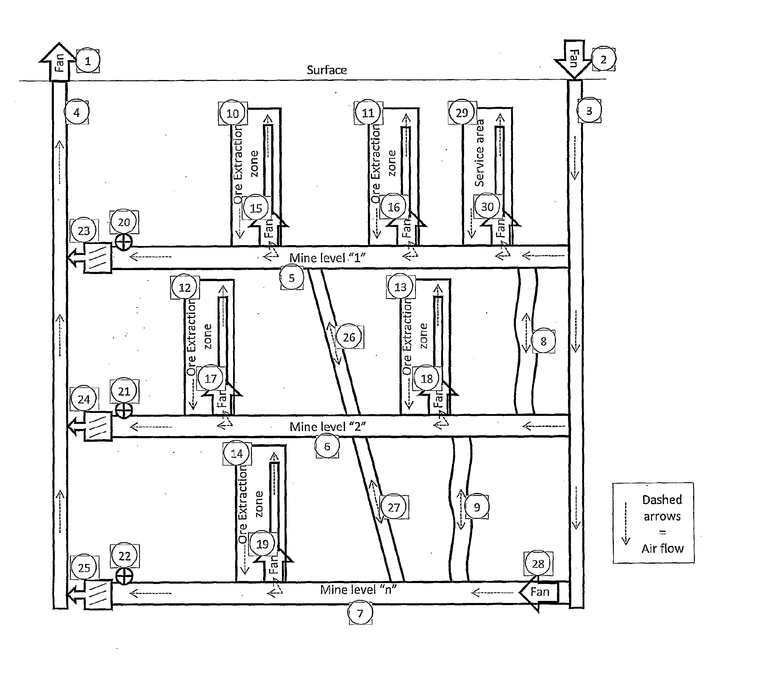
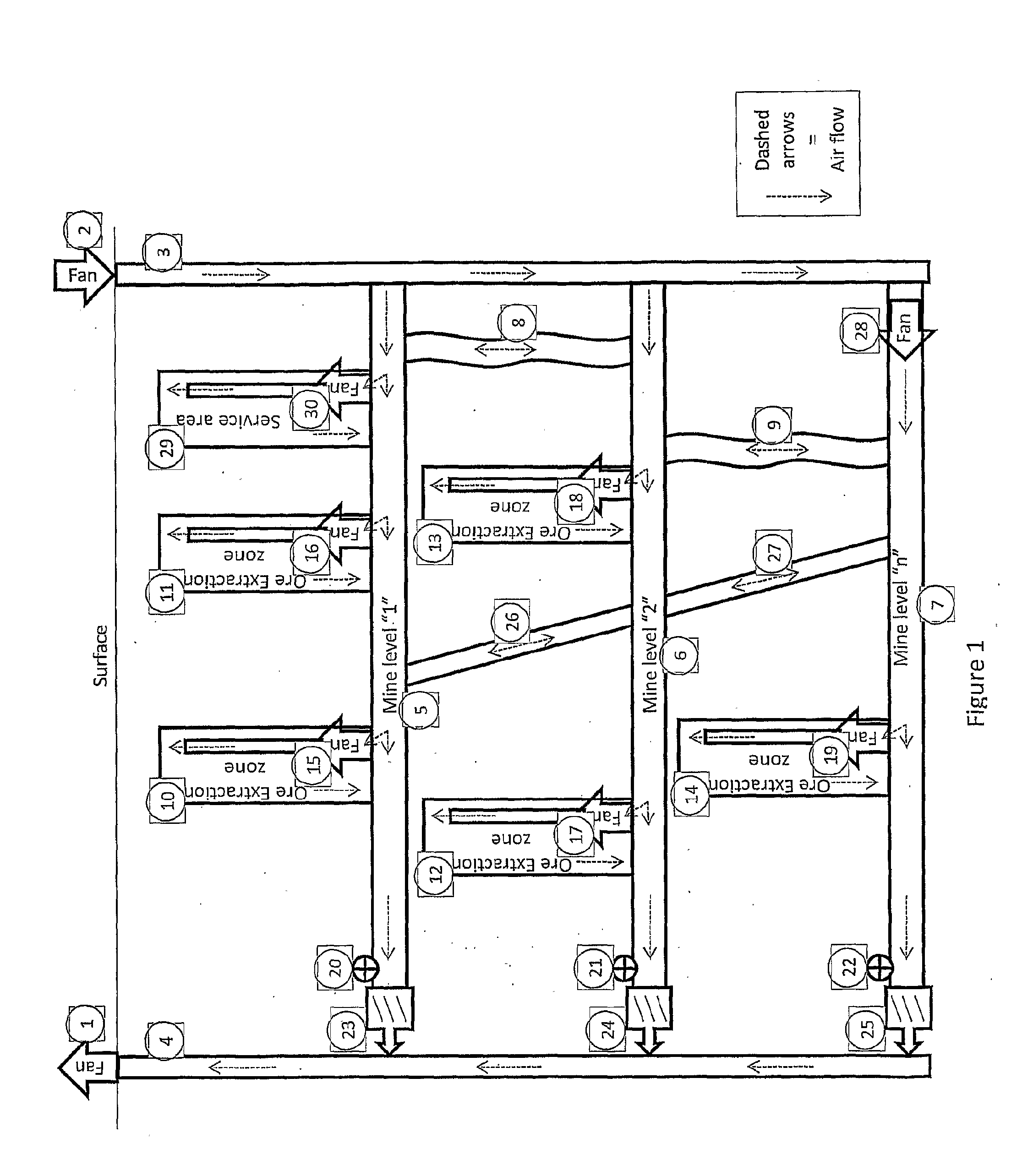
[0075]A novel optimized mine ventilation system will be described hereinafter. Although the invention is described in terms of specific illustrative embodiment(s), it is to be understood that the embodiment(s) described herein are by way of example only and that the scope of the invention is not intended to be limited thereby.

[0076]An embodiment of the optimized mine ventilation system according to the present invention will be described below in detail with reference to the drawings.

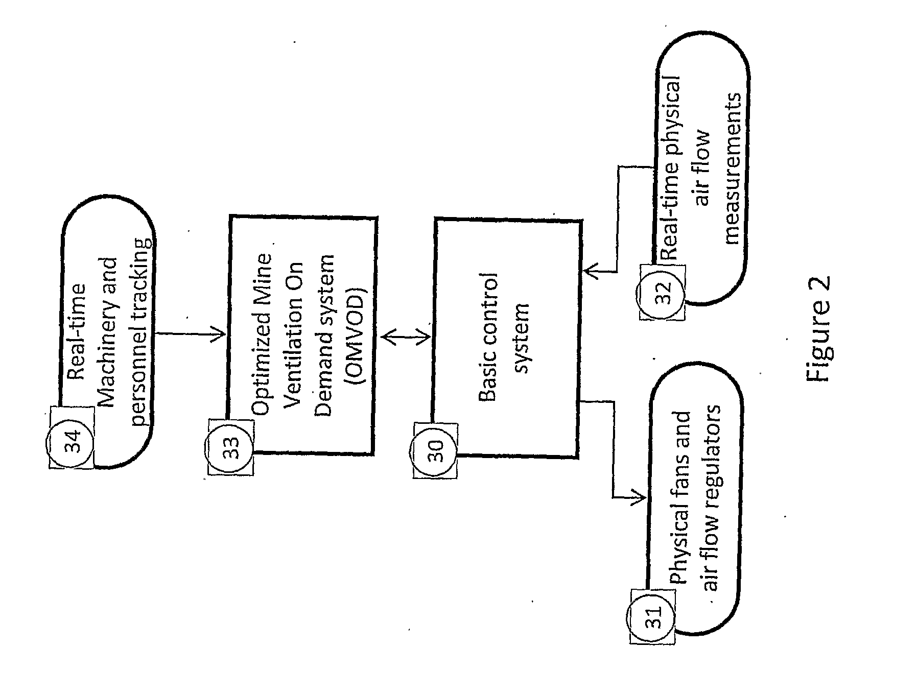
[0077]The following describes a summary of the optimized mine ventilation system functionality and links to external systems with references to FIG. 3.

[0078]A third party machinery and personnel tracking system provides real-time data on the machinery location and operating status and on personnel location [FIG. 3, item (55)].

[0079]From the dynamic tracking status of each machinery a ventilation demand is calculated for each defined mine work zones as per the following [FIG. 3, items (56, 57)]:[0080]CFM...


PUM


Abstract

The optimized mine ventilation system of this invention supplements mine ventilation basic control systems composed of PLCs (Programmable Logic Controllers with human machine interfaces from vendors such as Allen-Bradley™, Modicon™ and others) or DCSs (Distributed Control System from vendors such as ABB™ and others) with supervisory control establishing a dynamic ventilation demand as a function of real-time tracking of machinery and / or personnel location and where this demand is optimally distributed in the work zones via the mine ventilation network and where the energy required to ventilate is minimized while totally satisfying the demand for each work zones. The optimized mine ventilation system operates on the basis of a predictive dynamic simulation model of the mine ventilation network along with emulated control equipment such as fans and air flow regulators. The model always reaches an air mass flow balance where the pressure and density is preferably compensated for depth and accounts for the natural ventilation pressure flows due to temperature differences. Model setpoints are checked for safety bounds and sent to real physical control equipment via the basic control system.

Description

CROSS-REFERENCE TO RELATED APPLICATIONS[0001]The present patent application claims the benefits of priority of Canadian Patent Application No. 2,559,471, filed on Aug. 31, 2007, at the Canadian Intellectual Property Office and entitled: “Underground communication network system for personal tracking and HVAC control”.FIELD OF THE INVENTION[0002]The present invention generally relates to mining underground ventilation control and its optimization as a function of a dynamic demand related to the tracking of the machinery location and / or operating status and / or personnel location. More specifically it relates to the predictive modeling and simulation along with the optimization of the air distribution and fans energy consumption to physically control the operating setpoints for fans and air flow regulators.BACKGROUND OF THE INVENTION[0003]FIG. 1 represents a typical mine ventilation layout with airflow control equipment. The intent is not to generalize the FIG. 1 layout example to all ...

Claims


Application Information

Patent Timeline
Patent Type & Authority Applications(United States)
IPC IPC(8): E21F1/00G05B13/02
CPCY02B60/50E21F1/00G05B15/02G05B17/02Y02P80/10G05B2219/2614Y02P90/80E21F1/003G05B19/042
Inventor MASSE, MICHEL
Owner HOWDEN CANADA INC
Why Eureka
Try Eureka