Method and Apparatus for Spectral Cross Coherence

a spectral cross coherence and apparatus technology, applied in the direction of optical radiation measurement, multi-channel direction-finding systems using radio waves, instruments, etc., can solve the problems of high signal to noise ratio, high computational cost, and low resolution performance of capon-mvdr algorithm, so as to improve resolution performance and improve resolution performance

Active Publication Date: 2010-04-29
MASSACHUSETTS INST OF TECH
View PDF15 Cites 36 Cited by
  • Summary
  • Abstract
  • Description
  • Claims
  • Application Information

AI Technical Summary

Benefits of technology

[0013]The system may apply a spectral estimation filter to the data and compute the measure of cross coherence to improve resolution performance. The system may obtain the data from a finite set of observations taken over time and assembled into a matrix. The system may obtain the

Problems solved by technology

A maximum-likelihood (ML) formulation leads to a M-dimensional spectral search algorithm where M is the number of signals present in the data, and therefore can be computationally very expensive.
Indeed, when sources are wel

Method used


Image

  • Method and Apparatus for Spectral Cross Coherence
  • Method and Apparatus for Spectral Cross Coherence
  • Method and Apparatus for Spectral Cross Coherence

Examples


numerical examples

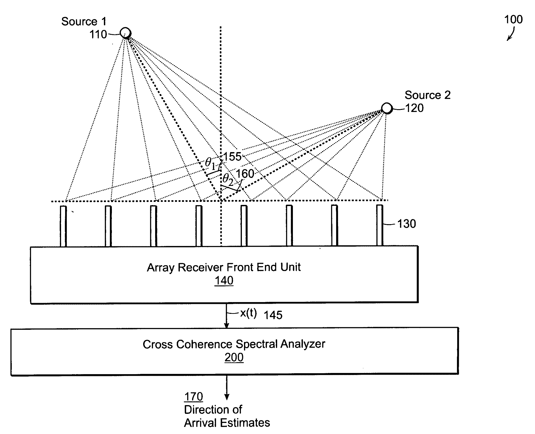
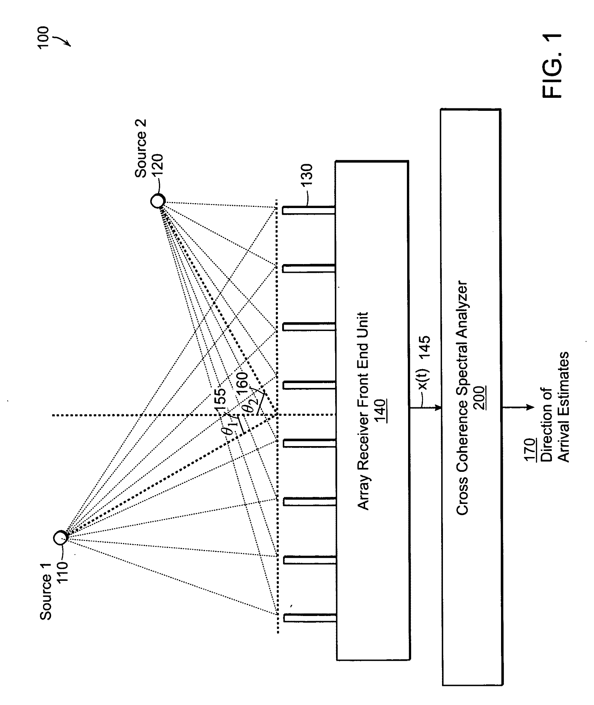
[0064]Consider a Direction of Arrival (DOA) estimation scenario involving two equal power planewave sources and a set of signal bearing snapshots

x(l)∼CN[0,I+∑k=12σSk2v(θk)vH(θk)](18)

l=1, 2, . . . , L for an N=18 element uniform linear array (ULA) with slightly less than λ / 2 element spacing, and L=3N snapshots. The array has a 3 dB beamwidth of 7.2 degrees and the desired target signals are placed at θ1=90 degrees (array broadside), θ2=93 degrees (less than half a beamwidth separation).

[0065]FIG. 4 illustrates the cross spectrum estimate PCB(θa, θb) shown by the gray color scale. Plotted on top of this image are normalized versions of the Capon 420 and MUSIC algorithm 410 1-D spectra for comparison. This is an example for which the MUSIC algorithm 410 was able to resolve two signals at σSk2=1 dB, but the Capon algorithm 420 has failed. The cross spectrum 430, however, shows two distinct peaks 435, 440 located at the same angles as the two peaks of the MUSIC algorithm 410, but obtaine...


PUM


Abstract

The present invention relates to a machine implemented method for spectral analysis that determines a measure of cross coherence between application of two spectral estimation filters to data; and identifies a spectral feature of the measure of cross coherence. One example embodiment of the present invention provides a complete statistical summary of the joint dependence of the Bartlett and Capon power spectral statistics, showing that the coupling is expressible via a 2×2 complex Wishart matrix, where the degree coupling is determined by a single measure of cross coherence defined herein. This measure of coherence leads to a new two-dimensional algorithm capable of yielding significantly better resolution than the Capon algorithm, often commensurate with but at times exceeding finite sample based MUSIC.

Description

RELATED APPLICATIONS[0001]This application claims the benefit of U.S. Provisional Application Nos. 61 / 123,357, filed Apr. 8, 2008 and 61 / 124,042, filed on Apr. 14, 2008. The entire teachings of the above applications are incorporated herein by reference.GOVERNMENT SUPPORT[0002]This invention was supported, in whole or in part, by Naval Sea Systems under Air Force contract FA 8721-05-C-0002. The government has certain rights in the invention.BACKGROUND OF THE INVENTION[0003]In radar systems, where one of the goals is localizing a target, which may be a boat, an aircraft, an automobile, or a subsurface object, a signal (e.g., a propagating electromagnetic or acoustic wave) emanates from the target and arrives at a sensing location. The sensing location may include an array of sensors. Among the goals of the sensing location is often to estimate the relative direction of the target object. For this purpose, the concept of direction of arrival estimation is used to identify the directio...

Claims


Application Information

Patent Timeline
IPC IPC(8): G01R13/00
CPCG01S3/74
Inventor RICHMOND, CHRIST D.
Owner MASSACHUSETTS INST OF TECH
Why Eureka
Try Eureka