Partially Self-Refueling Low Emissions Vehicle and Stationary Power System

a technology of stationary power system and self-refueling, which is applied in the direction of machines/engines, mechanical equipment, transportation and packaging, etc., can solve the problems of crippling the world's energy-dependent free market economy, burdening businesses and consumers worldwide, and complicating the problem of global warming, so as to optimize the cumulative beneficial effect

Active Publication Date: 2010-05-06
MORIARTY DONALD E
View PDF76 Cites 82 Cited by
  • Summary
  • Abstract
  • Description
  • Claims
  • Application Information

AI Technical Summary

Benefits of technology

[0013]In light of the problems and deficiencies inherent in the prior art, the present invention seeks to overcome these by providing a method and device to optimize the cumulative beneficial effect of harvesting energy that is otherwise lost to inefficiencies and energy sources that are available in the natural environment. The cumulative energy that is recovered and otherwise collected is converted to electrical energy which power

Problems solved by technology

The challenge of global warming is further complicated by the daunting spectres of energy embargos, petro-terrorism, and diminishing petroleum reserves, all of which threaten to cripple the world's energy-dependent free market economies.
Moreover, the rise of crude oil prices from early January to September 2008 proved to be burdensome for businesses and consumers worldwide.
However, it has been suggested that a major drawback with increasing the number of electric and hybrid-electric vehicles in use is the large quantities of batteries to power the electric motors and other electrical devices.
If improperly charged, batteries can be permanently damaged.
Additionally, if left uncharged for long periods of time, the batteries can deteriorate and become unusable.
Moreover, battery storage is heavy, space consuming, offers maintenance challenges and offers limited life.
Batteries used typically for vehicles of the state-of-art have an average effective life of 8 to 10 years and must be disposed of after their lifecycle, thereby creating a highly toxic environmental hazard.
Although conventional piston-type inter

Method used


Image

  • Partially Self-Refueling Low Emissions Vehicle and Stationary Power System
  • Partially Self-Refueling Low Emissions Vehicle and Stationary Power System
  • Partially Self-Refueling Low Emissions Vehicle and Stationary Power System

Examples


Embodiment Construction

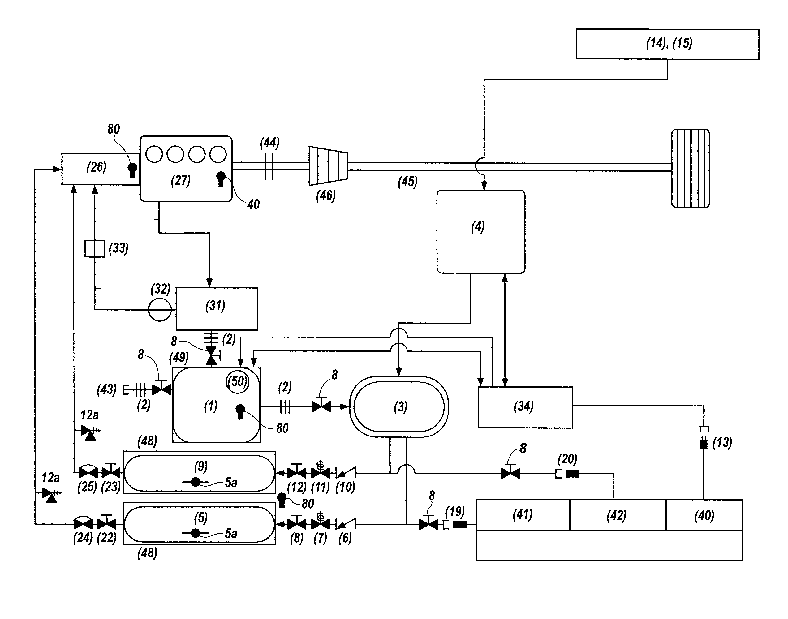
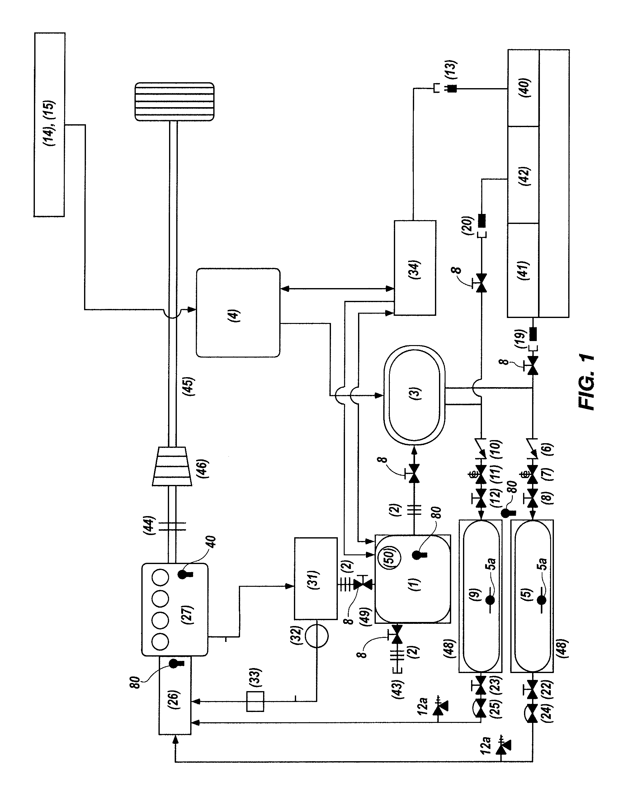
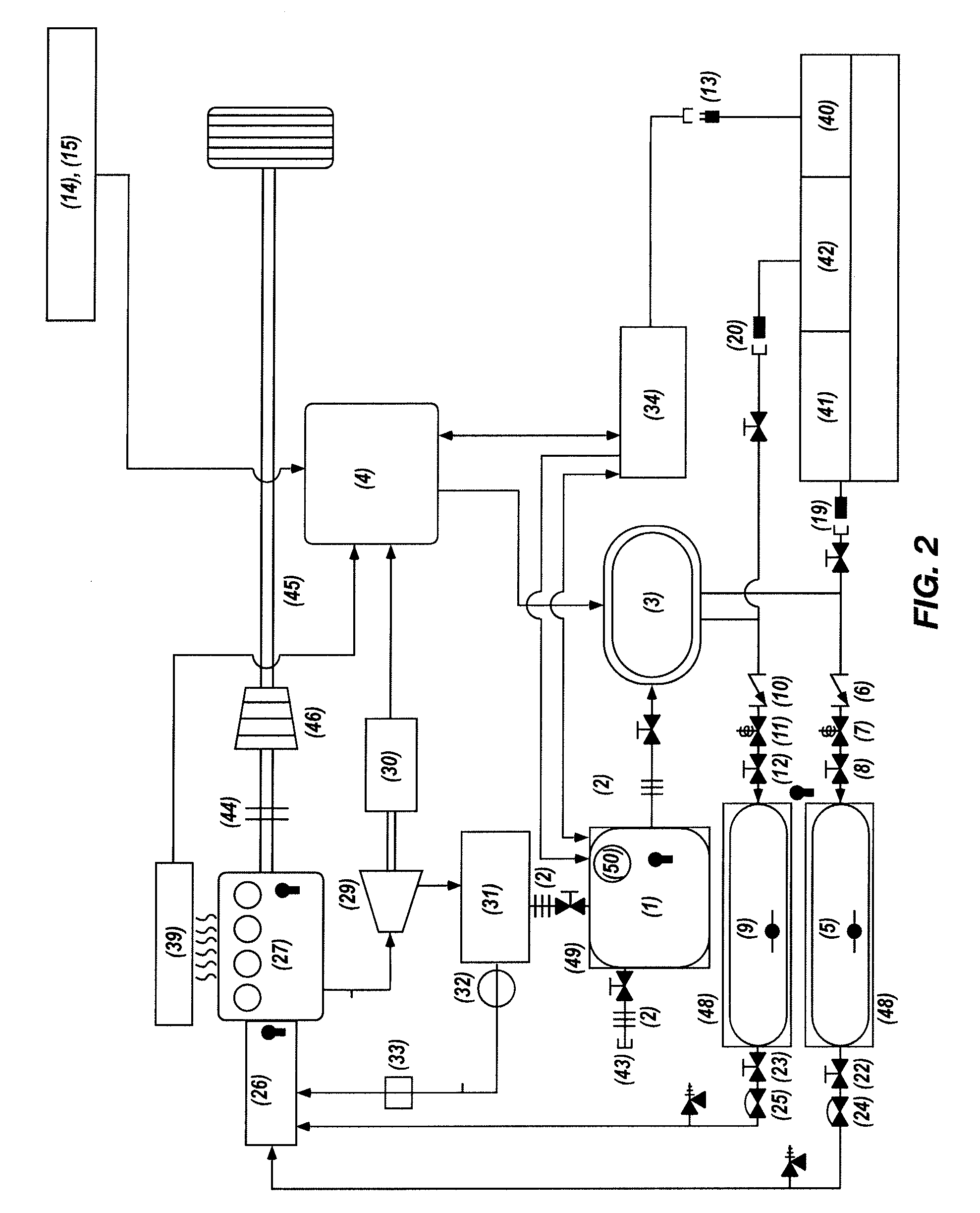
[0035]The following description of exemplary embodiments of the invention makes reference to the accompanying drawings, which form a part hereof and in which are shown, by way of illustration, exemplary embodiments in which the invention may be practiced. While these exemplary embodiments are described in sufficient detail to enable those skilled in the art to practice the invention, it should be understood that other embodiments may be realized and that various changes to the invention may be made without departing from the spirit and scope of the present invention. Thus, the following more detailed description of the embodiments of the present invention is not intended to limit the scope of the invention, as claimed, but is presented for purposes of illustration only. The following description also sets forth the best mode of operation of the invention, and is sufficient to enable one skilled in the art to practice the invention. Accordingly, the scope of the present invention is ...


PUM


Abstract

A method and device to optimize the cumulative beneficial effect of harvesting available forms of lost energy, including energy that is lost while a vehicle is in motion (e.g., kinetic energy and energy contained in electromagnetic radiation. The cumulative energy that is recovered is converted to electrical energy which powers the on-board electrolyzer to produce more hydrogen and oxygen while the system is in operation and stationary. Stationary, passive forms of energy (e.g., solar, wind, hydro, etc.) will also be available to power the electrolyzer. The system also contemplates using passive forms of energy to power a non-mobile system which incorporates an internal or external combustion engine in place of a fuel cell. An oxygen injection control device is employed to control the supply of oxygen to the combustion engine.

Description

PRIORITY CLAIM AND RELATED APPLICATIONS[0001]This application is a continuation-in-part and claims the benefit of U.S. patent application Ser. No. 12 / 425,264 filed Apr. 16, 2009 which claims priority to U.S. Provisional Application No. 61 / 124,469 filed on Apr. 16, 2008, each of which are incorporated herein in their entirety.FIELD OF INVENTION[0002]The present invention relates to clean air engine systems, more particularly to clean air engine systems using electrolysis of water to generate the gases to fuel an internal or external combustion engine, fuel cell or other device.BACKGROUND OF THE INVENTION[0003]Early in 2009, the United States Environmental Protection Agency categorized carbon dioxide and five other harmful gases as major health risks that threaten the planet. Similarly, the European Parliament passed a new set of vehicle emissions standards designed to reduce carbon dioxide creation by nearly thirty percent by 2020. Furthermore, leaders in the United Nations, fearing ...

Claims


Application Information

Patent Timeline
IPC IPC(8): F02B43/08F02B47/02H02K21/14
CPCF03G7/08Y02T10/7072
Inventor MORIARTY, DONALDTONER, STEPHEN
Owner MORIARTY DONALD E
Why Eureka
Try Eureka