

Direct current drive land vehicle
a direct current drive and land vehicle technology, applied in the field of land vehicles, can solve the problems of inefficient transmission and drive train use of low gearing exclusively
- Summary
- Abstract
- Description
- Claims
- Application Information
AI Technical Summary
Benefits of technology
Problems solved by technology
Method used
Image


Examples
Embodiment Construction
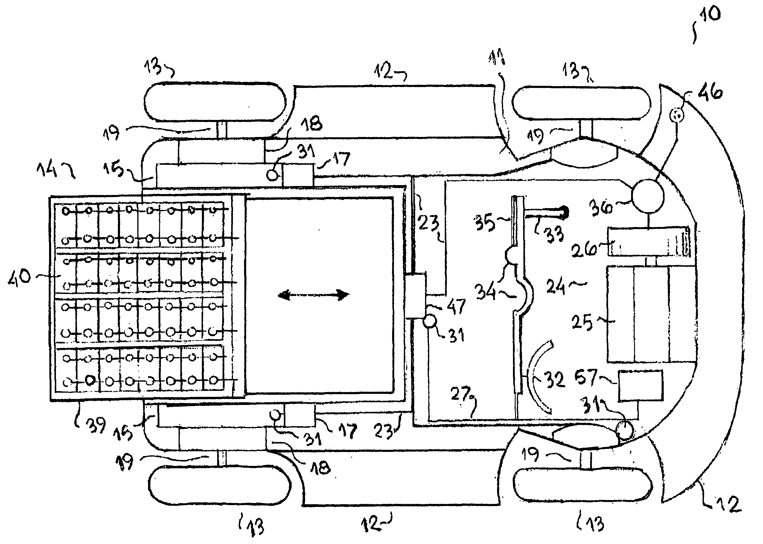
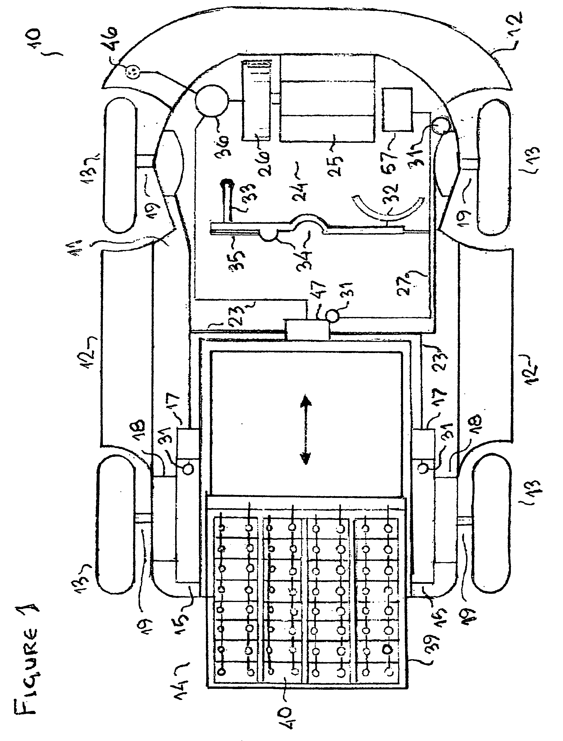
[0038]A direct current drive land vehicle (DCDLV) 10 in accordance with the principles relating to the present invention is seen in FIG. 1 with a chassis 11, and a body 12: preferably, but not necessarily, removably attachable to a standard chassis 11 and comprised of one of many different models of land vehicles, as suggested by the three models of bodies 12 shown FIGS. 3, 5&6; having fully electric drive in accordance with said principles and depicted in detail in FIG. 2, said electric drive having at least one DC reversible field motor (DCRFM) 15 with an output shaft 16 coupled to one wheel 13 driven by that DCRFM 15 through planetary gearing 18, providing regenerative braking and obviating the need for a conventional automotive drive train including central transmission.
[0039]DC power storage 14 is necessary to a DCDLV 10 in accordance with the principles relating to the present invention. The lead acid batteries 40 seen in FIG. 1 comprise the most preferred embodiment of DC pow...
PUM
 Abstract
Description
Claims
Application Information