
Apparatus For And Method Of Automatically Welding Flange Of Guide Thimble Tube In Nuclear Fuel Assembly

a technology of automatic welding and guide thimble, which is applied in the direction of auxillary welding devices, nuclear elements, greenhouse gas reduction, etc., can solve the problems of time-consuming, difficult to manufacture guide thimbles in an automatic way, and difficult automatic welding, so as to prevent diseases in the musculoskeletal system, improve productivity, and improve the effect of productivity

Active Publication Date: 2010-05-06
KEPCO NUCLEAR FUEL CO LTD
View PDF34 Cites 18 Cited by
  • Summary
  • Abstract
  • Description
  • Claims
  • Application Information

AI Technical Summary

Benefits of technology

The present invention provides an apparatus and method for automatically welding a flange to a guide thimble tube in the manufacturing process for guide thimble tubes. The apparatus and method automate the welding process, improve productivity, prevent diseases in the muscles, and improve product quality. The apparatus includes a welding part, a flange supplying part, and a conveying part. The flange supplying part piles up flanges and discharges them one by one. The welding torch group automatically welds the flange and tube. The apparatus and method automate the process of transferring the tube and flange onto the welding part. The conveying part includes axially and laterally conveying means for the tube. The laterally conveying means includes a cam unit and a conveyable body. The apparatus and method improve automation and productivity.

Problems solved by technology

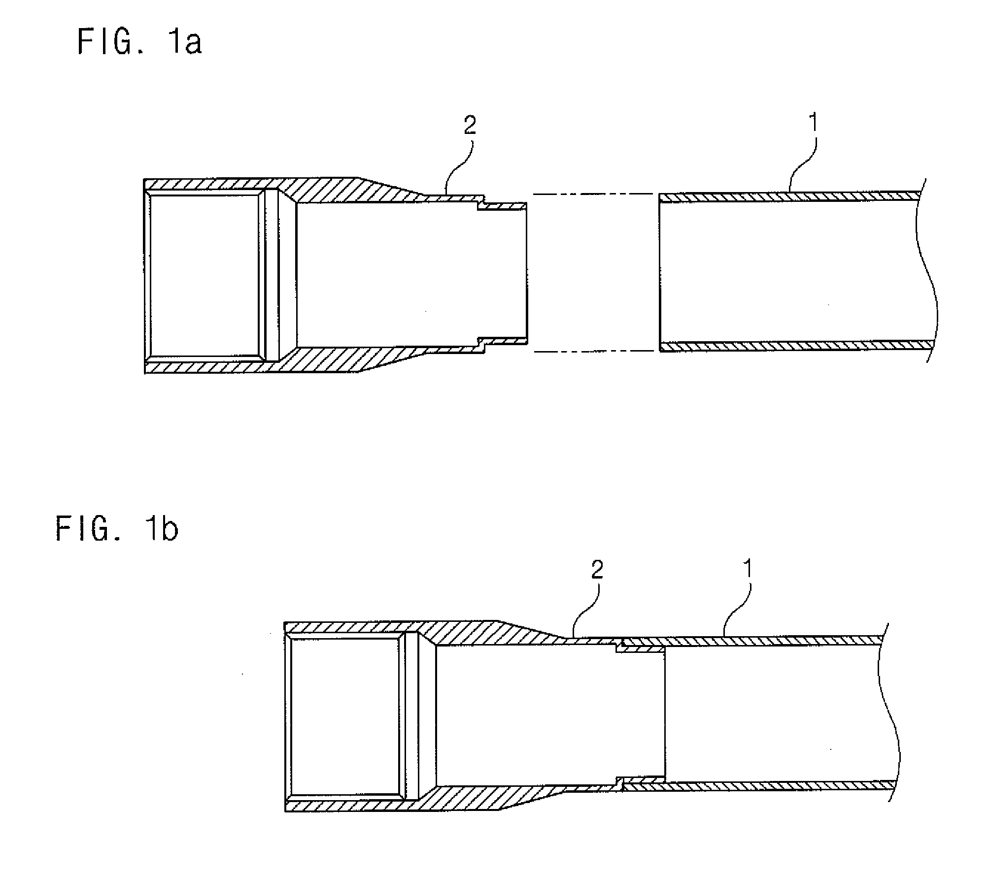
The guide tube having the above-described structure had a sophisticated shape and thus it is very difficult to manufacture the guide tube in an automatic way.
Therefore, since the welding of a flange or the like to the guide tube must be performed with a great precision, a manual manufacturing process has been carried out for the purpose of quality, which leads to a time consuming.
As previously mentioned, it is because the shape of the guide tube is not simple and thus an automatic welding is not easy.
In addition, in case of manually working on a larger amount of guide tubes, there is a concern about diseases in the musculoskeletal systems, due to the tube length of about 4000 mm and weight of about 2.5 kg.
Furthermore, in terms of productivity and quality, the working time is extended and not consistent to degrade its production efficiency.

Method used


Image

  • Apparatus For And Method Of Automatically Welding Flange Of Guide Thimble Tube In Nuclear Fuel Assembly
  • Apparatus For And Method Of Automatically Welding Flange Of Guide Thimble Tube In Nuclear Fuel Assembly
  • Apparatus For And Method Of Automatically Welding Flange Of Guide Thimble Tube In Nuclear Fuel Assembly

Examples


Embodiment Construction

[0054]Reference will be now made in detail to the preferred embodiment of the present invention with reference to the attached drawings.

[0055]If there is no specific definition and description, the terms used to indicate upper and lower directions and left and right directions are defined with reference to the attached drawings, and it is noted that unnecessary indications of sections in the drawings will be omitted in order to facilitate identification.

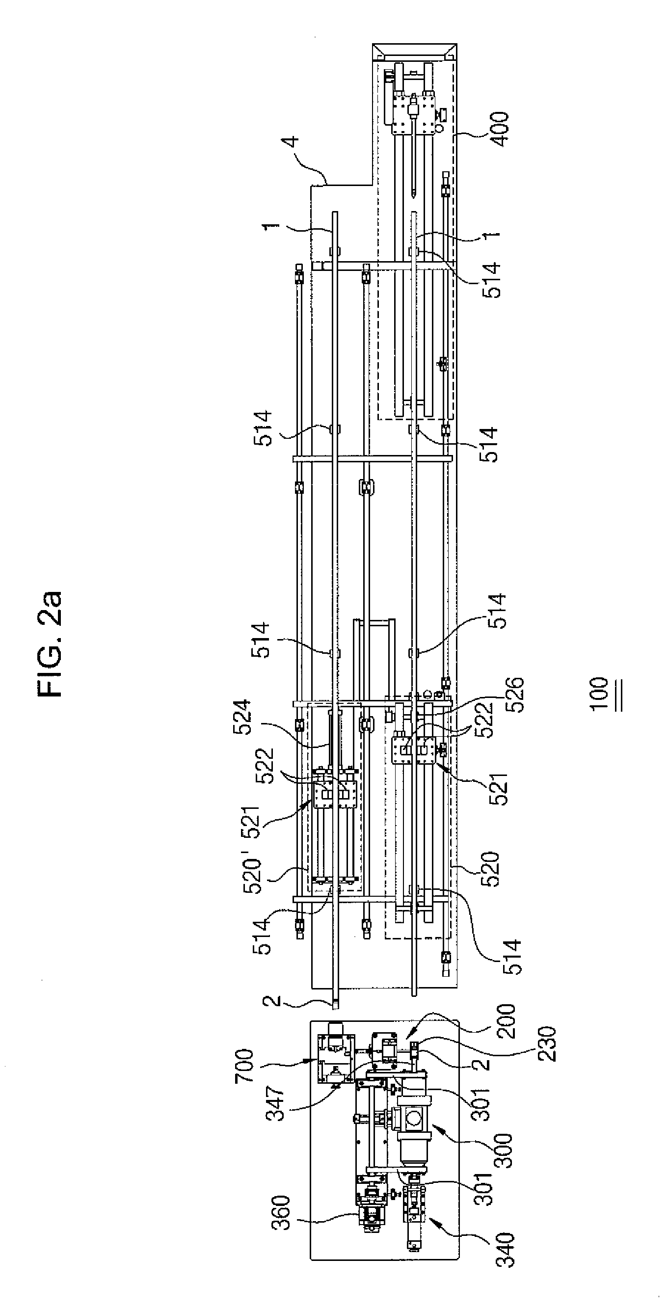
[0056]FIG. 2a is a top view of an apparatus 100 for automatically welding a flange of a guide thimble tube, and FIG. 2b is a front view of the apparatus 100 for automatically welding the flange of the guide thimble tube.

[0057]As shown in FIGS. 2a and 2b, the apparatus 100 for automatically welding a flange of a guide thimble tube (hereinafter, called ‘automatic welding apparatus’) includes a flange supplying part 200 mounted on a workbench 4, a welding part 300, a stopper side sealing unit 400, a conveying part 500, a tremor measurin...


PUM

PropertyMeasurementUnit
lengthaaaaaaaaaa
weightaaaaaaaaaa
lengthaaaaaaaaaa

Abstract

Disclosed therein are an apparatus for and a method of automatically welding a flange to a guide thimble tube in a nuclear fuel assembly. The automatic welding apparatus includes: a welding part located on an axially conveying line of a tube for welding a welded surface of the tube inserted thereinto and a welded surface of a flange; a flange supplying part for supplying the flange at a tube inlet of the welding part onto the axially conveying line; and a conveying part mounted on the axially conveying line in such a way as to move the tube and the flange on the axially conveying line, so that they are inserted into and drawn from the welding part.

Description

BACKGROUND OF THE INVENTION[0001]1. Field of the Invention[0002]The present invention relates to an apparatus for and a method of automatically welding a flange to a guide thimble tube in the manufacturing process for the guide thimble tube, which is a major element of a nuclear fuel assembly.[0003]2. Background of the Related Art[0004]A nuclear fuel assembly is an assembly of fuel elements that can be handled in one entity when loaded into and unloaded from a nuclear reactor. For example, a nuclear fuel assembly used for a light-water reactor (called a fuel assembly) is composed of a plurality of fuel rods (fuel elements) forming a bundle of a rectangular shape, at both ends of which a perforated support plate is disposed to pass coolant, and at the intermediate of which a support grid is mounted for the fuel rods to be spaced apart from each other. The individual fuel rod is formed of a hollow zicaloy tube having a length of about 4 mm, inside of which sintered uranium pellets are...

Claims


Application Information

Patent Timeline
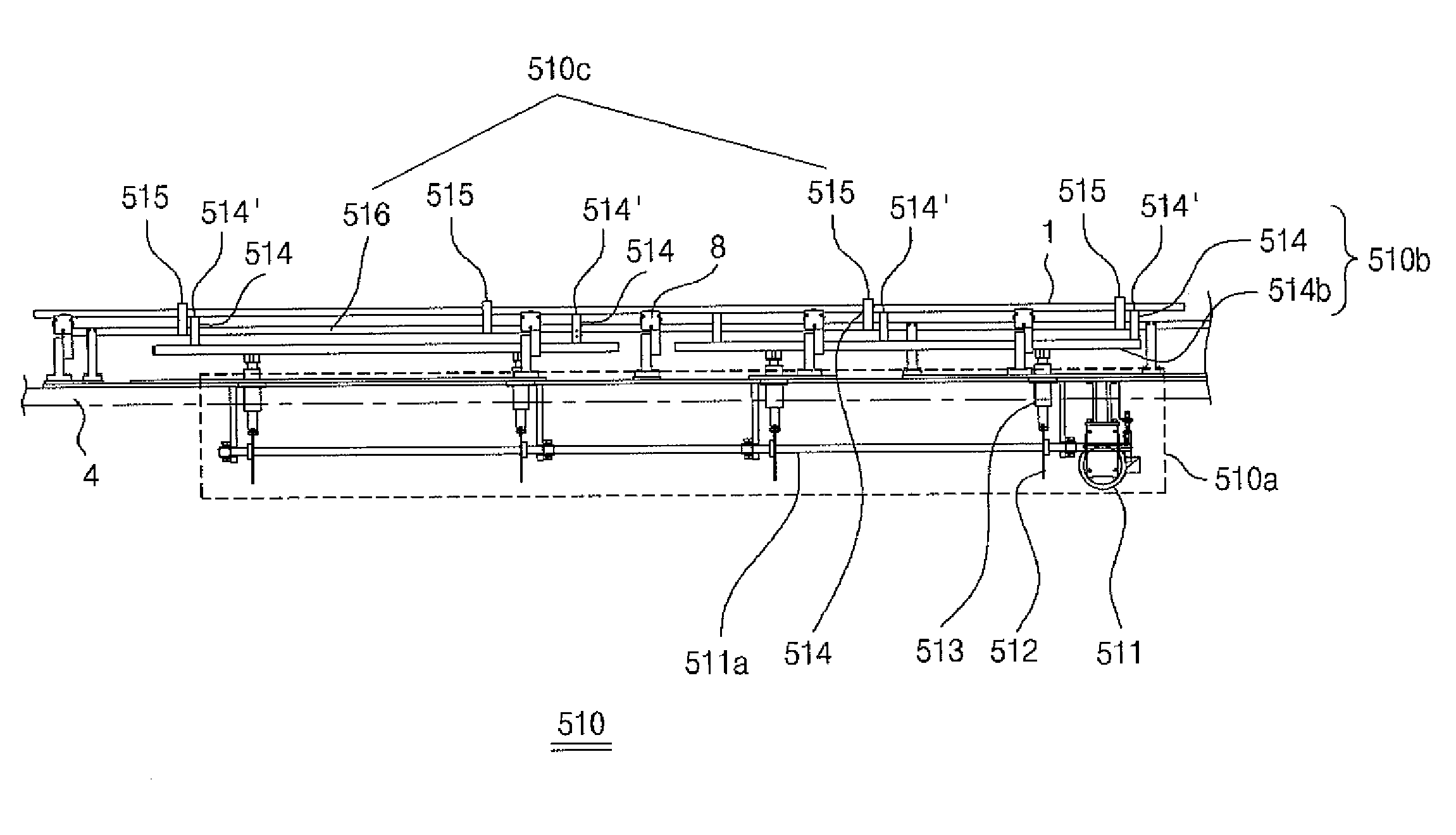
Patent Type & Authority Applications(United States)
IPC IPC(8): B23K20/00B23K31/00B23K37/04
CPCB23K9/0286B23K31/02B23K33/006B23K37/0235B23K37/0247B23K37/027G21C21/02B23K37/0426B23K37/0536G21C3/326Y02E30/38B23K2101/06B23K37/0276Y02E30/30
Inventor KWON, KI-JUNSHIN, SE-YONGKONG, SANG-PILCHANG, HUNG-SOONKIM, JEONG-HONA, TAE-HYUNG
Owner KEPCO NUCLEAR FUEL CO LTD
Learn More